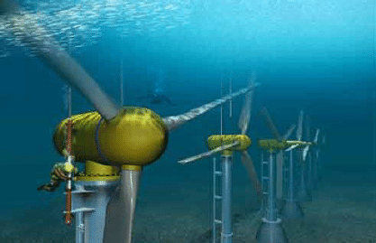
Axial flow turbines are turbines in which the working fluids flow parallel to the shaft despite the radial turbines where the fluids rotate around the shaft like in a watermill. An axial turbine has the same structure as the axial compressor but works in reverse. In other words, the axial flow turbine converts the fluid flow into rotating mechanical energy.
Horizontal axis turbines, often known as axial flow turbines, are quite similar to standard horizontal axis wind turbines. A vertical beam attached to the seafloor is where axial flow turbines’ blade-equipped rotors are mounted. The turbine begins to spin and produce electricity as the current flow spins the blades. Several Suppliers and Companies, as well as various manufacturers and distributors, have introduced axial flow turbines, and there are many Axial Turbines for Sale on Linquip.
The Linquip website has a comprehensive list of Turbine Services for all OEM fleets. Vendors for Linquip can help you with this. For more information on how to connect with a wide collection of service providers who continuously produce high-quality products, please get in touch with Axial Turbine Experts in Linquip.
A set of stator guide vanes or nozzles accelerates and gives additional swirl to the fluid, and leads it to the turbine blades row installed on a turbine rotor.
Types of Axial Flow Turbines In Terms of Working Fluids
According to the working fluid, axial flow turbines can be steam turbines, gas turbines, hydraulic turbines, horizontal axis wind turbines, or ocean current turbines.
Axial Flow Steam Turbines
Steam turbines operate to convert the thermal energy available in the steam into mechanical energy. They are used for electricity generation in thermal power plants. The steam is guided through the turbine to multistage rotating blades driving the electric generator. Such power plants utilize natural gas, fossil fuel, coal, or nuclear fuel.
A steam turbine is a heat engine that obtains much of its advancement in thermodynamic efficiency using multiple stages, which leads to a closed condition to the ideal reversible expansion procedure. Because the turbine creates rotating motion, it is especially suitable for driving an electrical generator. For example, in 2014, about 85% of all electricity in the U.S. was generated by the use of steam turbines. A turbo generator is a steam turbine that is attached to an electric generator.
The development of steam turbines was years before the gas turbines. Therefore, the design of the axial flow gas turbines is the result of the growth of steam turbine technology.
Axial Flow Gas Turbine
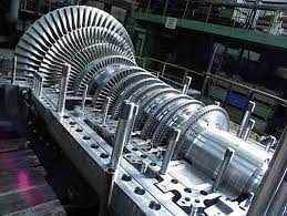
Axial flow turbine is the most broadly utilized gas turbine using a compressible fluid. Axial flow turbines supply most gas turbine units and are more efficient than radial turbines in most working ranges. Gas turbines are combustion engines at the heart of a power plant converting natural gas or other fuels to mechanical energy. Then, the energy runs the generator that generates electrical energy.
The high-temperature pressurized gas from the combustion engine enters the gas turbine and produces a shaft work output. This work also causes the compressor to drive; the remaining energy leaves to be repurposed for external work, including directly generating thrust in a turbojet engine, and rotating a second independent turbine connected to a fan, propeller, or electrical generator.
Types in Terms of Energy Conversion Method
Accordingly, axial flow turbines can be divided into two general categories: Impulse turbines and reaction turbines. In the impulse turbine, the entire enthalpy drop takes place between the nozzles; therefore, the flow velocity entering the rotor is very high. On the other hand, the structure of a reaction turbine is such that the enthalpy drop occurs between the nozzle and the rotor.
Impulse Turbine
The impulse turbine has the simplest basics among all turbines. A gas turbine includes a set of nozzles followed by a row of blades. The gas expands in the nozzle, its high thermal energy converts into kinetic energy. It can be represented by the following equation:
V_{inlet}=\sqrt{2\Delta h_{0}}
The high-velocity gas hits the blade, and much of the kinetic energy of the moving gas flow turns into turbine shaft work.
The following figure demonstrates a schematic diagram of a single-stage impulse gas turbine. In the nozzle, the static pressure decreases as the absolute velocity increases. Then, the absolute velocity reduces in the rotor; however, static pressure and relative velocity do not change.
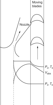
For maximum energy transfer, the blades have to rotate at about half the velocity of the gas jet. Two or more moving blade rows are sometimes applied with one nozzle to lower blade tip speeds and stresses of the wheels. There are guide vanes between the moving blade rows redirecting the gas from one moving blade row to another -the Curtis turbine- (the next figure).
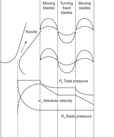
Another impulse turbine is the Ratteau turbine, in which the work is done along various stages. Each stage includes a nozzle and blade row. So, a portion of the entire kinetic energy of the jet flow is absorbed by each stage of the turbine as useful work. The air that exits the first row of moving blades enters the next set of nozzles to further reduce the enthalpy. The velocity is increased, and another part of kinetic energy is absorbed in the associated row of moving blades.
In the following figure, the velocity and pressure distribution of the flow is shown through a Ratteau turbine. It should be noted that the total pressure and temperature remain constant in the nozzles, except for some frictional losses.
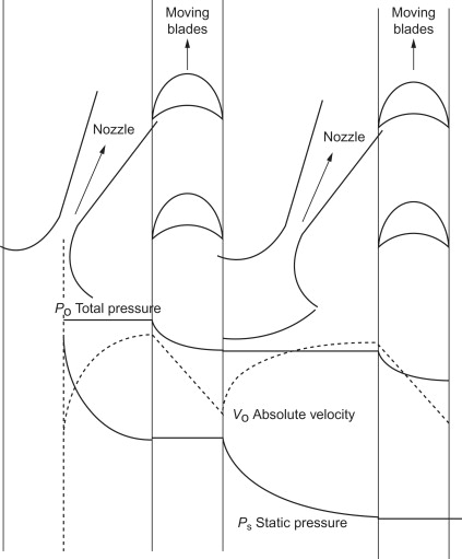
The entire enthalpy drop in an impulse turbine is taken in the nozzle, and the outlet velocity from the nozzle is high. Thus, by definition, the degree of reaction of an impulse turbine is equal to zero. Because no change in enthalpy occurs in the rotor, the relative velocities entering the rotor and exiting from the rotor blade are equal. The absolute exit velocity must be axial to obtain the maximum utilization factor. Thus, the air angle (α) can be calculated by:
\cos \alpha=\frac{2U}{V_{inlet}}
Subscript ‘inlet’ represents the turbine rotor inlet and U is blade speed. Usually, α is small, from 12° to 25°.
The optimal value of U/Vinlet is a measure that indicates the maximum energy transfer to the shaft. It also represents the deviation from the desired design value of cos α, leading to a loss of energy transfer. At off-design conditions, the losses increase due to the incorrect gas attack angle concerning the rotor blade. The maximum stage efficiency occurs at or near the value of α expressed above.
The power generated by the flow with an impulse turbine is determined using the Euler equation:
P=\dot{m}U(V_{\theta,inlet}-V_{\theta,outlet})
In the above equation, Vθ is the tangential component of the absolute velocity.
For the maximum utility factor, this equation can be rewritten as:
P=\dot{m}U(V_{\theta,inlet}\cos \alpha)
In a pure impulse turbine, the relative velocity remains unchanged, except for the effects of friction and turbulence. The loss may vary from about 20% for high-velocity turbines to about 8% for low-velocity turbines.
Reaction Turbine
The axial flow reaction turbines are the most widely used. In a reaction turbine, the nozzles and blades both work as expanding nozzles. So, the static pressure reduces in the fixed and moving blades.
The fixed blades serve as nozzles and guide the flow toward the moving blades at a velocity somewhat greater than the velocity of the moving blades. In a reaction turbine, the velocities are normally much lower, and the relative velocities entering the blade are almost axial. The following figure illustrates a schematic view of a reaction turbine.
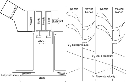
The 100% reaction turbine (a turbine with a degree of reaction equal to 1) is not practical due to the high rotor speed required for a good utilization factor.
The 50% reaction turbine is widely used and has particular strengths. The velocity diagram for such a reaction turbine is symmetrical and the outlet velocity must be axial to reach the maximum utilization factor. The angles of the stationary and the rotating blades are the same. Hence, for maximum utilization, we have:
\cos \alpha=\frac{U}{V_{inlet}}
The power produced by the reaction turbine is calculated using the general Euler equation:
P=\dot{m}U(V_{\theta,inlet}\cos \alpha)
The work produced by an impulse turbine with a single-stage operating at the same rotational speed is twice that of a reaction turbine. Therefore, the cost of a reaction turbine is much higher for the same amount of work because it needs more stages. Additionally, the efficiency of a reaction turbine is higher due to blade suction effects.
Thus, it is very common that impulse stages in the first few stages of a multistage turbine followed by 50% reaction turbines are used to maximize the pressure decrease. This combination leads to an effective agreement because an all-impulse turbine has very low efficiency and an all-reaction turbine has an excessive number of stages.
Axial Flow Hydraulic Turbines
In hydraulic turbines, the working fluid is water. A very common example of the axial hydraulic turbine is the Kaplan turbine. The hydraulic turbine is a turbomachine that turns the potential energy available in an elevated water body (such as a river or reservoir) into rotational mechanical energy.
Kaplan is a propeller-type water turbine that applies the principle of reaction turbines to extract the energy of the fluid by the changes in water pressure passing the turbine.
Where Are Axial Turbines Used?
Thermal power plants are employed for the production of energy. The turbine directs the steam to the multistage spinning blades that power the electric generator. These power stations run on coal, natural gas, fossil fuels, or nuclear energy.
Axial Flow Wind Turbine
Horizontal axis wind turbines have axes of rotation horizontal to the ground and nearly parallel to the wind stream. Most commercial wind turbines are of these turbines. Horizontal axis wind turbines have axes of rotation horizontal to the ground and nearly parallel to the wind stream. Most commercial wind turbines are of these turbines. A wind turbine converts the wind’s kinetic energy into mechanical energy. This can be directly applied for mechanical purposes such as pumping water or grinding grains and also generating electricity.
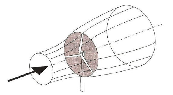
Axial Flow Marine Turbines
Axial flow marine turbines are very similar to typical horizontal axis wind turbines explained above. The rotors of these turbines, equipped with blades at one end, are mounted on a vertical beam that is fixed on the seabed. When the current flow turns the blades, the turbine spins and generates electrical energy.
The energy harnessed by an axial flow turbine can be maximized as the swept area of the blades covers the current flow direction. Therefore, in some forms of axial flow turbines, the rotor can yaw depending on the direction of the current flow.
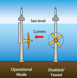
The total power supplied by a marine turbine considering the losses is determined using the following equation (similar to a wind turbine):
P=0.5C_{p}\rho A V^{3}
Where ρ is the fluid density, A is the swept area of the axial flow turbine, V is the fluid velocity, and CP is the power coefficient which normally varies between 0.35-0.5 for marine turbines.
Download Axial Flow Turbines PDF
Buy Equipment or Ask for a Service
By using Linquip RFQ Service, you can expect to receive quotations from various suppliers across multiple industries and regions.
Click Here to Request a Quotation From Suppliers and Service Providers
Read More In linquip
- What is Mixed Flow Turbine? Basics, Advantages, and Applications
- Radial Flow Turbine
- Cross-Flow Turbine: Working Principle, Components, and Advantages
- What are Hydrokinetic Turbines? Working Principles and Output Power
- What is Propeller Turbine? Types and Working Principles
- What is Tesla Turbine and How Does it Work?
- Hydrogen Gas Turbine: All You Need to Know
- Mixed Flow Turbine
- The 8 Best Home Wind Turbines in 2021
- Types of Turbines: Classifications and Types

