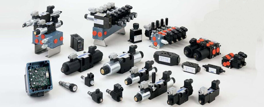
There are many types of hydraulic valves available in the industry. Hydraulic valves are mechanical equipment for controlling the flow of fluid in hydraulic pipes or systems. They can be utilized to thoroughly check the flow level to a specific domain, redirect pressurized fluid or close a line.
Hydraulic valves can be used to control the flow of fluid in a circuit as well as the quantity of fluid power. As a result, the pressure and flow rate in various portions of the circuit would be controlled by these valves. Hydraulic valves can regulate system pressure. The hydraulic valve relieves the pressure on the pump or lowers the temperature of the oil before it enters the hydraulic circuit. Different types of hydraulic valves are accessible from a wide range of Suppliers and Companies, as well as manufacturers and distributors, and Linquip has a large selection of Hydraulic Valves for Sale.
Linquip’s website has a comprehensive list of hydraulic valve services for all OEM fleets. Suppliers of Linquip can help you with this. To learn more about how to connect with a varied collection of service providers who consistently produce high-quality products, please contact Hydraulic Valves Experts in Linquip.
⇒ View a Comprehensive List of Valves and Their Suppliers ⇐
Types of Hydraulic Valves
Hydraulic valves are available in various characteristics similar to other valves, such as bypass, needle, regulating, relief, ball, butterfly, pilot-operated, check, diverter, proportional, and directional. In general, these hydraulic valves may be described as being of three main varieties which are:
- Hydraulic Flow Control Valves
- Hydraulic Pressure Control Valves
- Hydraulic Directional Control Valves
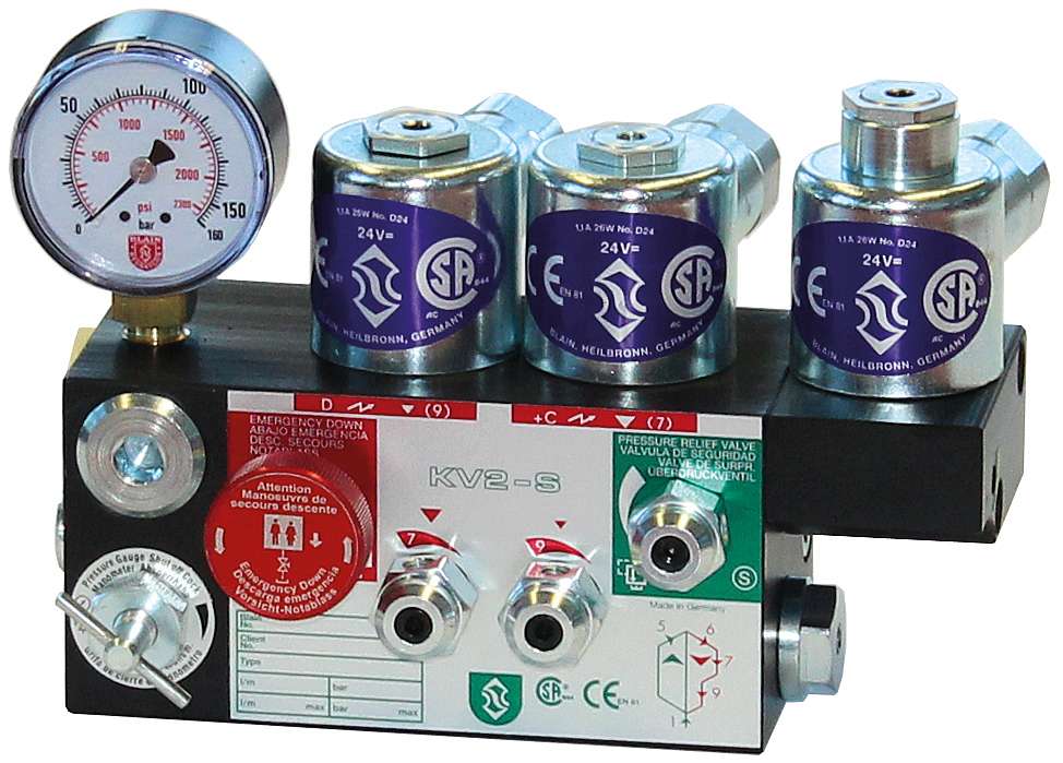
Hydraulic Flow Control Valves
Hydraulic flow control valves are used to regulate the flow volume of passing fluid in hydraulic systems. These types of valves have a movable gate that changes the flow domain to modify the flow rate in the valve. For example, this type of hydraulic valve would be used in control circuits for devices, such as actuators, cylinders, or motors. The speed of these devices is a function of flow rate linearly, i.e. decreasing the flow rate reduces their driving speed and vice versa.
The different types of hydraulic flow control valves are movable flow control valves, pressure compensated flow control valves, fixed flow control valves, and throttling flow control valves. The method of flow control in these valves are modifying based on the mechanical shape of the valve, which regularly is one of the well-known styles same as other valves, namely:
- Ball
- Butterfly
- Diaphragm
- Needle
- Plug
We can measure flow rate in many distinct ways, which are not similar, so choosing a flow control valve demands understanding what is expected by flow rate. The three standard types of flow rate are:
- Mass flow rate – we measure the mass per unit time in the units such as the kg/min or slugs/sec.
- Weight flow rate – we measure weight per unit time in the units such as lb/sec.
- Volumetric flow rate – we measure volume per unit time in the units such as the cc/min or in3/sec.
Some of the conventional hydraulic flow control valves are:
- Pressure-compensated proportional flow-control valves
- Deceleration valves
- Proportional flow-control logic valves
- Pressure- and temperature-compensated, variable flow valves
- Pressure-compensated, variable flow valves
- Priority valves
Hydraulic Pressure Control Valves
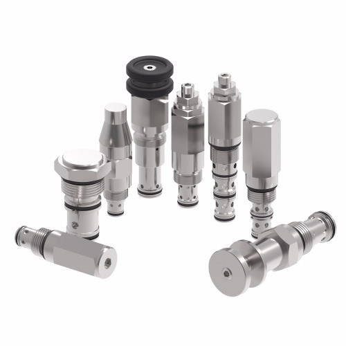
Hydraulic pressure control valves are used to regulate the fluid pressure passing through hydraulic arrangements to keep that pressure at desired amount as restricted by the system operator. Fluid systems are typically produced for operation at a fixed range of pressures. These valves serve a crucial role in preventing rises in pressure that may result in hydraulic fluid leaks or the bursting of pipes and tubes. They are also installed to have the desired pressure in some sections of a hydraulic circuit.
Several kinds of pressure control valves are widespread in hydraulic systems, including reducing valves, relief valves, sequence valves, counterbalance valves, and unloading valves.
See All Control Valve for Sale
Hydraulic Directional Control Valves
We use hydraulic directional control valves to track fluid in a system or circuit to several devices as demanded. They shift between discrete positions such as extend, retract, or neutral locations for controlling a hydraulic cylinder. They can also change into intermediate states to control an actuator’s acceleration, speed or direction.
Discrete hydraulic Directional control valves are a simple form of binary valves, passing blocking the fluid flow. If fluid tries to pass in the reverse direction, a check valve seals the system using a ball, plunger or poppet.
Hydraulic directional control valves with more complicated characteristics may have multiple gates, as their characteristics allow them to switch fluid within distinct ports depending on the device they supply with hydraulic fluid. Consequently, they are discriminated against by standardized numbering systems that have two values, the same as 4/3 or 2/2. The first number indicates the number of valve ports, and the second number indicates the number of valve positions that the device can achieve.
According to this coding scheme, 2/2 represents a two-state valve and 4/3 a four-state valve with three positions. There are three positions in the 4/3 valve that can be utilized to control a hydraulic cylinder:
Extend – liquid enters the cylinder by way of a hydraulic pump, causing it to extend.
Retract – liquid is introduced from the hydraulic pump to the rod end of the cylinder, which in turn causes it to retract.
Neutral – all liquid ports are blocked, so there is no flow of liquid.
Here we list some of the classes for directional-control valves. You can identify these valves according to the:
- The number of flow ways in the extreme positions.
- The number of spool positions.
- Method of providing spool return.
- Method of shifting a spool.
- Flow pattern in the crossover or center position.
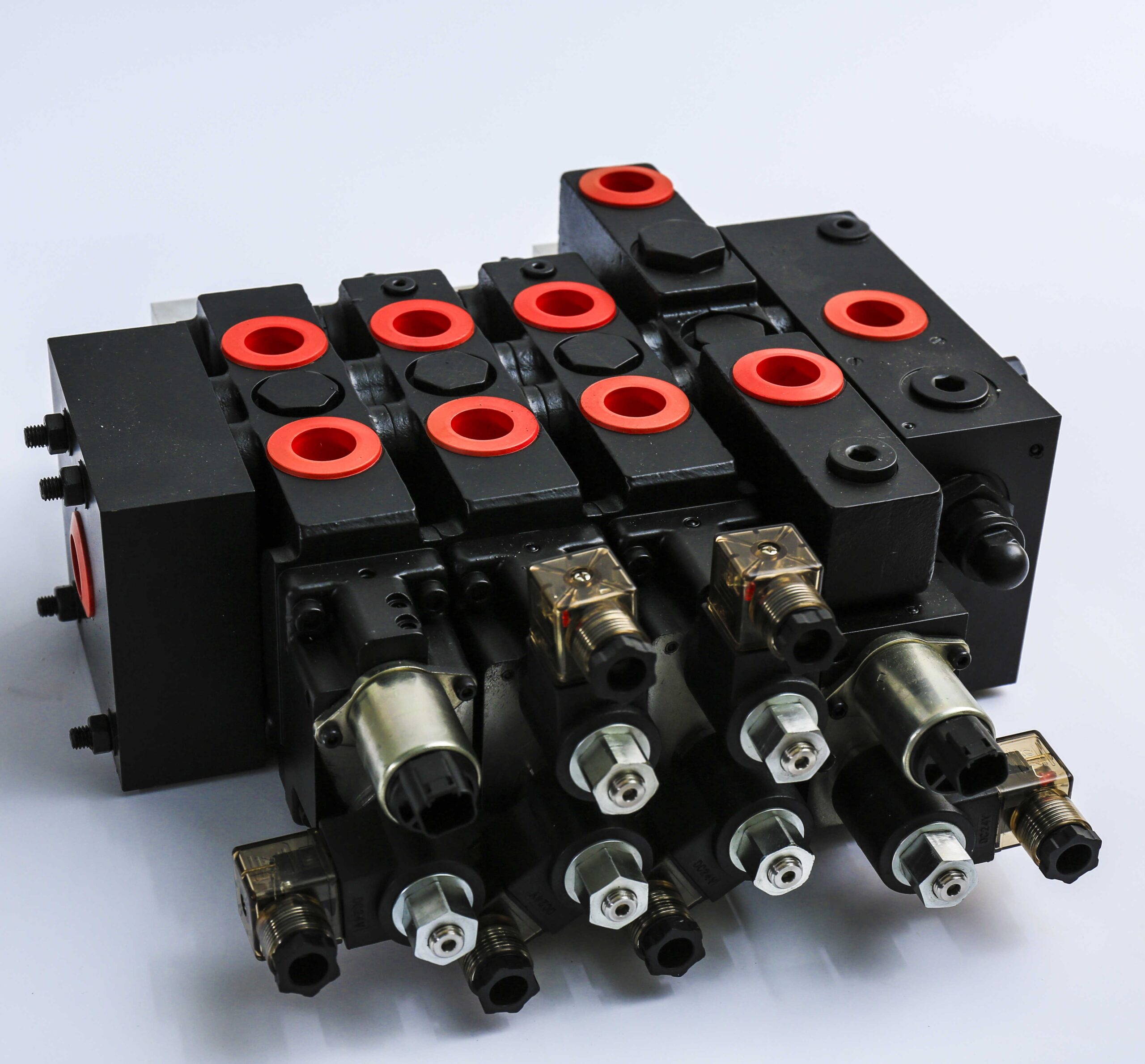
Hydraulic Four-Way Valves
Four-way directional-control valves are installed to manage the direction of fluid flow in a hydraulic line, which commands the direction of the rotation of a fluid motor or the movement of a working cylinder. These valves usually are the sliding-spool model. Standard four-way directional-control valves have four ports:
- The exit or return port is attached to a reservoir.
- The pressure line is connected to a pressure port.
- Two operating ports are connected to an actuating unit.
Four-way valves have a rectangular cast frame, a sliding spool and a way to locate a spool. A spool is a precision fitted to a bore by the longitudinal axis of a body. The lands of a spool partition this bore into a set of separate chambers. Ports in a valve’s body lead into a section so that a spool’s situation determines which ports are open and which ones are closed. Ports that are sealed off from others in one position may be interconnected in different positions. Spool positioning is completed mechanically, electrically, manually, or hydraulically.
The figure below shows how the spool location determines the possible flow states in the line. The four ports are labeled as P, T, A, and B: P is connected to the flow reservoir; T to the tank; and A and B to the ports of the working hydraulic motor, cylinder, or some other valve in the path. In figure A, the spool is in a position that port P is free to port A, and port B is free to port T. Ports A and B are joined to the ports of the cylinder, flowing through port P, and make the piston of the cylinder to travel to the right. Return flow from the cylinder moves through ports B and T. In figure B, port P is free to port B, and the piston travels to the left. Return flow from the cylinder reaches ports A and T.

The table below is presented all Types of hydraulic valves.
| Classification | Description | |
| Control type | Manual operated | The hand lever shifts the spool. |
| Pilot operated | Hydraulic pressure shifts the spool. | |
| Solenoid operated | Solenoid action shifts the spool. | |
| Solenoid controlled, pilot operated | Solenoid action shifts the integral pilot spool and directs the pilot flow to move the main spool. | |
| Path of flow type | Two way | Allows two possible flow paths in two spool positions |
| Four-way | Allows four possible flow paths in two spool positions | |
| Position type | Two-position | The spool has two positions of dwell. |
| Three-position | The spool has two positions plus one center or intermediate position. | |
| Spool type | Open center | include five of the common spool types. |
| Close center | ||
| Partially closed center | ||
| Semi-open center | ||
| Tandem center | ||
| Spring type | Spring offset | Spring action automatically turns the spool to the normal offset position when shifter force is released. (Spring offset is always a type of the two-way valve) |
| No spring | The spool is not spring-loaded; it is moved only by force, and it remains where it is moved (two- or three-position type, however, the three-position type uses detent). | |
| Spring centered | Spring action automatically turns the spool to the center position with releasing force. (Spring-centered is a type three-position valve.) | |
The function of the Hydraulic Control Valve
Several hydraulic directional control valves have spools. Spools slide between parts allowing liquid to flow in open gates, based on the state of the spool in the body. Valves may have one or multiple spools to achieve the designed port control. Other flow control elements in these valves may be poppets or plungers.
The valve part that drives these flow control components is known as the actuator or operator of the valve. These hydraulic valves can present proper timing or sequencing of the valve position modifications needing to control the hydraulic systems or circuits. There are many possibilities for the actuator mechanism, including pilot, electrical/electronic, mechanical actuation.
Mechanical Actuation_Mechanical actuation can have hand-operated valve controls such as levers, pushbuttons, or pedals, but more often are automated mechanical tools such as cams, levers, springs, and rollers.
Pilot actuation_Pilote actuation applies pressurized fluid to assist with moving the valve flow control elements. This operator style is also helpful in dangerous circumstances where electrical/electronic equipment performance may not be suggested because of the possible risk of causing an explosion.
Electrical/electronic actuation_Electrical/electronic actuation needs solenoids that convert electrical signals of current supplied to the solenoid coil into a plunger’s mechanical action that makes either rotary or linear movement. Electrical solenoids have some constraints in producing power, so switching high-pressure hydraulic systems by direct response is impossible. Coupling solenoid with pilot actuation allows the solenoids to switch lower pressure pilot operations to control higher pressure ports.
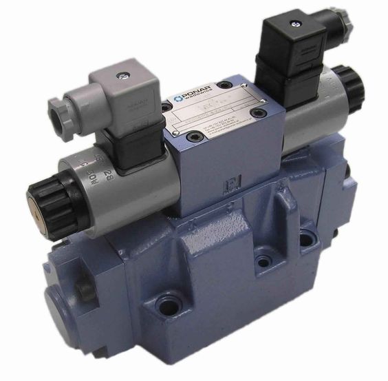
Hydraulic Valve Specifications
Hydraulic valves are specified utilizing several parameters related to their size, connections, flow capacity, and actuation mechanism. The typical properties for these valves are described below but remember that there can be exceptions in these parameters among different valve suppliers and manufacturers. So differences in design may exist from supplier to supplier. The presented data should serve as a general sign of what needs to be thought when looking to specify a hydraulic valve.
- Valve type_refers to the particular hydraulic valve type needed, which may display the physical style (ball, check, needle, etc.) or may refer to the control being explored (flow control, pressure control, or directional control).
- Valve actuation mechanism_ reflects how the valve position is changed or how the valve is operated, such as a solenoid, pilot, or mechanical.
- Valve configuration_ indicates the number of ports, the number of switching positions or states, and the specified rest state for the valve, e.g., 3/2 normally closed (NC).
- Body material_classifies the material from which the valve body is manufactured: brass, bronze, aluminum, stainless steel, or engineered plastic.
- Media type –identifies the type of the specific fluid (liquid or gas) for which the valve can handle without any deleterious effects. Examples of media types include oil, fuel, and water.
- Port size_shows the dimensional sizes for the inlet and outlet ports of the valve, designed in metric units such as millimeters or imperial units such as inches.
- Port type (or mounting type)_classifies the desired mounting/interface or port-style for the valve, such as manifold, flanged, threaded, etc.
- Operating voltage_is for electrically actuated valves and indicates both the magnitude and type of electrical control signal applied to energize the valve solenoid. Solenoid valves are prepared with a wide range of AC and DC working voltages that may be used to give different application conditions.
- Operating frequency_for AC voltage powered electrically actuated valves; frequency is the number of cycles per second of the alternating current connected to the solenoid, known usually in Hertz (for example, 60 Hz).
- Flow coefficient_the flow coefficient (Cv) of the valve measures the valve’s capacity to allow the flow of fluid through it. The conventional definition of flow coefficient is that it expresses the volume of water (in U.S. gallons) that will flow through the system at a temperature of 60oF in a one-minute period of time when there is a one psi pressure drop (outlet-inlet differential pressure) across the valve. Larger values of flow coefficient mean a larger amount of flow.
- Flow rate_rather than flow coefficient, valve suppliers may define the valve’s flow rate in units such as liters or gallons per minute.
- Maximum rated pressure_is the maximum pressure that the valve can work when installed in the hydraulic circuit.
- Minimum operating pressure_displays the lowest pressure in the system for the valve to operate effectively. While many direct operated valves can work at 0 bar pressure, indirect operated valves may need a minimum pressure to exist that can be used to support valve actuation. Some valves are designed using a pressure range.
- Operating temperature or temperature range_shows the prescribed range of temperatures over which the valve has been produced to function.
- Application_indicates the expected use or market for the valve, including elevators, chemicals, or aircraft. The understanding of industry may help bring to the surface additional qualifications or specifications necessitated by these working conditions.
- Buy Equipment or Ask for a Service
- By using Linquip RFQ Service, you can expect to receive quotations from various suppliers across multiple industries and regions.
Click Here to Request a Quotation From Suppliers and Service Providers
Read More on Linquip
- Ball Valve Manufacturers
- Butterfly Valve Manufacturers
- Needle Valve Manufacturers
- Plug Valve Manufacturers
- Diaphragm Valve Manufacturers
- What is Plug Valve
- What is Pressure Reducing Valves
- What is Safety & Relief Valves
- What is Seat Valves
- What is Solenoid Valve
- Plug Valve Suppliers and Companies
- Valve Parts Suppliers and Companies
- Pneumatic actuators Suppliers and Companies
- Solenoid Valve Suppliers and Companies
- Regulating & Pressure Reducing Valve Suppliers and Companies
- Control Valve Types101: Different Classifications, Advantage and Disadvantages
- Types of Pneumatic Valves: Specifications and Working Principles
- Globe valve types: basic types plus bold pros and cons
- Easy Intro to Electronic Expansion Valve
- Globe valve types: basic types plus bold pros and cons
- The 10 Best Sprinkler Valves in 2022
- The 6 Best Tubeless Valve Stems in 2022
- Thermal Expansion Valves: Everything You Need To Know
- 6 Main Types of Expansion Valves: an Easy to Understand Guide
- Strainer Valve: a basic guide to know it better
- Working Principle of Control Valve with Diagram
- Difference Between Gate Valve and Globe Valve
- Everything You Need To Know About Check Valve Function
- 10 Types of Water Valves: The 2022 Ultimate Guide
- Gate Valve vs Butterfly Valve: Comprehensive Guide in 2022
- Best Check Valve for Sump Pump: 9 of the Best Models
- 6 Different Shower Valve Types + Pictures: Your 101 Guide!
- Backflow Valve Installation, Costs and Maintenance in 2022
- How to Install a Thermostatic Mixing Valve? (Costs and Maintenance in 2022)
- How to Install a Water Pressure Reducing Valve? (Costs and Maintenance in 2022)
- Check Valve Installation Costs and Maintenance in 2022
- The 10 Best Water Shut off Valves of 2022
- What is Drain Valve? Working Principle, Types & Applications
- What are Coaxial Valves? Working Principles and Type
- What is Isolation Valve? Working Principle & Types



Thank you for sharing valuable information with us. This article has a lot of helpful information about LPG valves.