The principal difference between FDM and TDM is the way of transmitting multiple signals in the realm of time and frequency. Both FDM and TDM are two multiplexing methods in order to transmit various signals through only a single channel.
This means that in FDM, several signals are transmitted from several frequency-generating sources with different frequencies at the same time. But in TDM, each source is assigned a period whose signal is transmitted through a single channel to be transferred.
By sharing as much information about industrial equipment and tools as possible on the Linquip website, we hope to make your decision as informed as possible. For questions about multiplexers or their associated equipment, Linquip is the best platform to contact. Please feel free to contact Linquip’s experts with any questions you may have about these devices. Get a basic understanding of Linquip’s electrical component options by reading the article titled “What Is Electrical Component?“.
Linquip consists of a variety of components, so getting started with your Linquip Expert profile is the first step toward making use of them as effectively as possible. When you create an account with Linquip, you are going to be able to showcase your experience in the field of industrial equipment in a way that is tailored specifically to the needs of the industry. Are you interested in contributing as a guest poster to the Linquip website? Using the Guest Posting option, you can directly publish content on the Linquip platform.
In the present article, first, both FDM and TDM methods are introduced in the context of multiplexing, then the difference between FDM and TDM is explained in terms of their operation keys.
What is Multiplexing?
Multiplexing is a way of transmitting multiple signals through a channel. But the transmission of multiple signals is very challenging. But, the multiplexing technique makes it feasible.
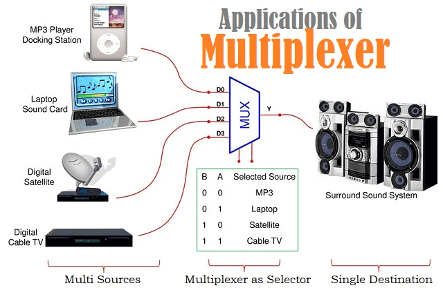
There are generally two types of multiplexing: Analog multiplexing, and Digital multiplexing.
Analog Multiplexing
When multiple analog signals are combined into a single analog signal, the process is called analog multiplexing. The multiplexing is done according to their frequency or wavelength.
Multiplexing needs multiple signals to be kept separately in a way that they are not overlapped. This leads to separation at the endpoint. This goal is reachable by separating the frequencies of the signals.
Analog multiplexing itself is divided into two sub-categories: Frequency Division Multiplexing (FDM), and Wavelength Division Multiplexing (WDM). Among these categories, FDM is more popular.
Digital Multiplexing
Digital multiplexing refers to the operation of combining multiple digital signals into a single signal. The most well-known method of digital multiplexing is Time Division Multiplexing (TDM). Synchronous TDM and Asynchronous TDM are two types of Time Division Multiplexing.
Applications of Multiplexing
Data transmission techniques based on multiplexing are widely used in sending communication signals. Below are some of these applications.
- Multiplexing in satellites
- Multiplexing in telemetry
- Multiplexing in radio broadcasting
- Multiplexing in telephone networks
- Multiplexing in computer memories to carry the data from a memory location.
- Multiplexing in TV broadcastings
- Multiplexing in telecommunication systems
- Multiplexing in video processing
Advantages of Multiplexing
The advantages of using multiplexing include the following.
- The use of multiplexing reduces the complexity of the circuit and its components, decreasing the costs of the communication system.
- This system makes optimal use of bandwidth.
- A multiplexing system can pass several signals through one channel at the same time.
Disadvantages of Multiplexing
When transmitting data analog or digitally using a multiplexer, the signals must be synchronized.
What is Multiplexer?
The multiplexer is a circuit to shift analog, digital, or video signals as a combination system. It is a plain circuit that allows multiple analogs or digital data and combines them in a single signal and sends it through the shared communication channel.
There are many types of multiplexers, some of which are listed here.
- 2:1 Multiplexer which consists of two signal inputs, one control bit, and one output.
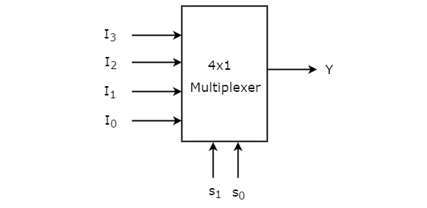
- 4:1 Multiplexer which consists of four signal inputs, two control bits, and one output.
- 8:1 Multiplexer which consists of eight signal inputs, three control bits, and one output.
- 16:1 Multiplexer which consists of four sixteen inputs, four control bits, and one output.
In the figure below, a 4:1 multiplexer block diagram is shown.
What Is FDM?
In telecommunications, FDM, which stands for frequency division multiplexing, is a system by which the entire ready bandwidth in a communication mechanism is arranged into a group of frequency bands that do not overlap. Each of them is responsible for transmitting a separate signal.
This provides a cable or optical fiber as single transmission media to be partaken by various independent signals.
The extra application is to perform the conduction of discrete serial bits and parts of higher signals in parallel.
The most typical case of frequency division multiplexing is devices like radio and television. In these cases, multiple radio signals with various frequencies pass over the air simultaneously. Another case is in cable television where numerous television channels are transmitted on a particular cable at the same time.
The technique of FDM indicates that across a channel, a particular frequency band is allocated to one signal.
In FDM, to adjust the signal of different data, a distinct frequency band is applied. In other words, different carrier frequencies are responsible for adjusting different signals transmitted through the channel. In addition, the mixed signal is set via a communication link to be transferred.
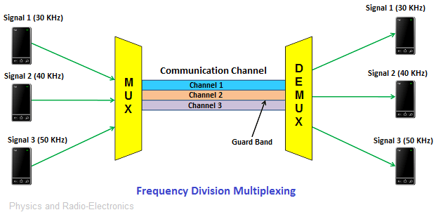
The following figure shows the multiplexing process using the FDM method.
How Does FDM System Work?
The above figure shows the FDM system schematically. As seen in the figure, there are multiple transmitters at the endpoint at the transmitter, and at the receiver end, there are multiple receivers. Between the transmitter and receiver, the communication channel is located to link the ends.
At the transmitter terminal, each transmitter gives a signal at different frequencies. For example, in the figure above, the transmitters send frequencies of 30, 40, and 50 Hz. These signals, which have different frequencies, are combined with a machine called a Multiplexer. This processed signal is then transmitted through a communication channel.
At the receiver terminal, the sent processed signals are again separated with the help of an apparatus called a demultiplexer. Its application is to send the separated signals to different receivers. For example, in the figure above, each of the receivers, numbers one to three receives 30, 40, and 50 Hz, respectively.
Applications of FDM System
Common applications of the FDM mechanism in communication media include the following.
- Application of FDM in the first generation of mobile phones
- Application of FDM in TV broadcasting
- Application of FDM to broadcast FM and AM radio waves
Advantages of FDM System
These systems have some significant advantages listed below.
- It is used to send multiple signals at the same time.
- In this system, it is easy to demultiplex the frequencies.
- There is no need for a process to synchronize the sender and receiver.
Disadvantages of the FDM System
The drawback of these systems is the need for a large bandwidth linking channel.
What Is TDM?
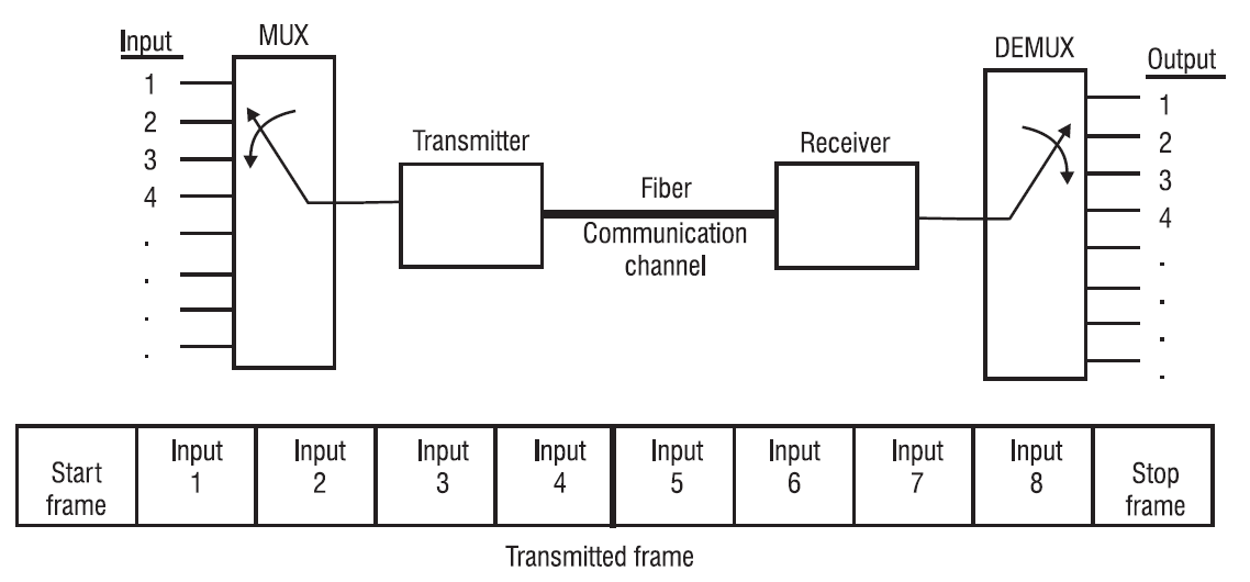
TDM or Time Division Multiplexing is a technique that allows several signals to be transmitted through one channel, one after the other. At the receiver terminal, the signals are separated and taken by the users. On this side, every user receives the corresponding signal at a different time.
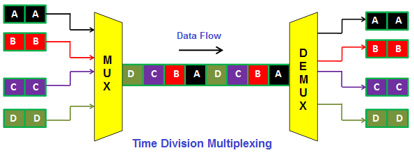
Unlike Frequency Division Multiplexing where signals of different frequencies are transmitted together, in Time Division Multiplexing, signals are transmitted at the same frequencies but at different times.
In other words, channel sharing in TDM is a time-based system, unlike the FDM method in which channel sharing is based on frequencies.
How Does TDM System Work?
In TDM, each user as a receiver is assigned a specific time slot during which data frequency is transmitted. Each of these time slots is very small.
In a TDM system, not all signals are sent at the same time, instead, they are sent sequentially. For example, in the figure above, signals A to D are sent in sequence, and thus each receiver allocates the bandwidth for a very short time.
TDM systems are used for both analog and digital multiplexing. But they are more suitable for the second type. In this multiplexing method, the capacity of the signal transmission channel must be greater than the capacity of each of the input signals, which leads to choosing the proper bandwidths.
Synchronous TDM
In synchronous Time Division Multiplexing, all transmitters are assigned with fixed time intervals. The device must send data within the allocated time slot. Even if they do not have a signal to transmit, this time is assigned to them and in this case, the time slot of the device without data is empty.
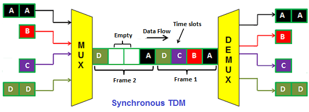
In the figure above, you can see the time frames, each of which can contain several time slots assigned to the transmitters. Equal to the number of transmitters, we will have time slots within each time frame.
The above schematic figure is interpreted as having four transmitters, which in Synchronous TDM are assigned four time intervals per time frame. Also in the second frame, you see that devices B and C do not have data to send, so their space is empty but the time allotted to them remains in place.
The disadvantage of these systems is that the bandwidth is not completely employed and a portion of that is wasted.
Asynchronous TDM
Asynchronous Time Division Multiplexing (also called statistical Time Division Multiplexing) is a multiplexing technique in which the time intervals are flexible and not fixed. In Asynchronous TDM, the number of time intervals and the number of transmitters are not equal, unlike synchronous TDM. In asynchronous TDM, the number of time slots is less than the number of transmitters.
In asynchronous TDM, time slots, such as simultaneous TDM, are not assigned to specific transmitters and are assigned to devices that want to send data.
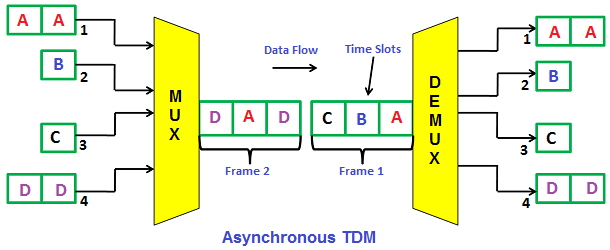
As shown in the figure, the number of time slots (3 in this figure) per time frame is less than the number of devices (4 in this figure). In the first time frame, the slots are occupied and the device that failed to send data in the first time frame (transmitter D) occupies the second time frame slots.
In this system, the multiplexer scans the transmitters and selects the ones that have real data to send to use the time slots with their data. Usually, all time slots are filled, but if there is not enough data for this purpose, partially filled time frames are transmitted.
Applications of TDM System
Here, a list of applications of TDM in telecommunication systems is presented.
- The earliest use of these systems in the telegraph.
- Using TDM in cellular radios.
- Using TDM in Satellite Access system.
- Use of TDM in Synchronous Optical Networking (SONET)
- Use of TDM in digital audio mixing system.
- TDM is the most common method for use in optical data transmission systems or fiber optic communication.
Advantages of TDM System
- The TDM method is a more flexible technique than the FDM method.
- In TDM, at a specific time, all the bandwidth is used by one user.
- In TDM, the undesirable transmission of signals between communication channels occurs rarely.
Disadvantages of TDM System
- A disadvantage of TDM over FDM is that TDM needs synchronization actions despite FDM which does not need.
- TDM has lower latency in comparison with FDM.
- TDM systems need to address the information and the buffer.
Most of the time, TDM and FDM systems are used on the same channel at the same time. Smaller frequency bands are created with the help of FDM in a channel. Each of these FDM channels is multiplexed using the TDM method. This is the way telecoms apply so that a large number of users can use common frequency bands.
In this video, you can learn some points about the difference between FDM and TDM.
Difference between FDM and TDM
Both FDM and BDM methods have been developed to transmit multiple signals through a single channel. However, given that the basis of their work is various, each difference between FDM and TDM will be mentioned in what follows.
Difference between FDM and TDM in Their Definitions
TDM and FDM mean Time Division Multiplexing and Frequency Division Multiplexing, respectively.
Difference between FDM and TDM in How the Signal Transmission Channel Is Used
The basic difference between FDM and TDM is in the way they divide the channel. FDM shares the channel for multiple frequency ranges that are not overlapping. But, the basis of the TDM technique is to divide and allocate particular time slots to each transmitter.
Difference between FDM and TDM in How the Bandwidth Is Occupied
In the FDM method, only part of the bandwidth is always occupied by one signal, but in the TDM method, in sections of time, all the bandwidth is filled by one signal.
Difference between FDM and TDM in Signal Types
TDM works well with both analog and digital signals. However, FDM can only work with analog signals.
Difference between FDM and TDM in Their Flexibilities
TDM system has more flexibility. Since it allocates more time slots to the signals requiring more bandwidth in a dynamic way, and besides, it reduces the time intervals for the signals that do not necessitate such a wide bandwidth. However, the FDM system lacks such flexibility and efficiency. FDM cannot adjust the width of the allotted frequency dynamically.
Difference between FDM and TDM in Their Interferences
Interference is low in the TDM system but high in the FDM system.
Difference between FDM and TDM in Their Efficiencies
As the probability of interference in TDM is low, its efficiency is high. But FDM efficiency is relatively low because it is more prone to be faced with interference.
Difference between FDM and TDM in Their Latencies
Latency is the time during which the data reaches its destination.
One of the benefits of the FDM system over the TDM system is that the data transfer speed from source to destination is faster in FDM. In TDM, since there is a time slot assigned to each transmitter and there is only one channel for transmission, there may be a time delay (in the range of a few milliseconds) for the transmission of some data.
But in the FDM system, data can be transferred at any time. So the latency in the FDM system is reduced. Thus in situations where the data transfer time is of paramount importance, FDM is used.
Difference between FDM and TDM in Their Constructions
TDM construction is simpler because of the type of wiring and chip, but more complex in FDM. So, the FDM technique is a more expensive multiplexing system than the TDM.
Difference between FDM and TDM in Required Inputs
A synchronization pulse is necessary for TDM, but a guard band is for FDM.
What Is the Reason for Using FDM in Analog Signals?
The FDM technology combines many modulated signals by providing a discrete carrier signal for each data stream. The FDM method is used to multiplex several analog signals. When a link’s bandwidth exceeds the combined bandwidth of the signals, FDM is applied.
Download FDM vs TDM PDF
You can download the entire content of this article by clicking on the following link.
Buy Equipment or Ask for a Service
By using Linquip RFQ Service, you can expect to receive quotations from various suppliers across multiple industries and regions.
Click Here to Request a Quotation From Suppliers and Service Providers
Read More In Linquip
- What is Frequency Division Multiplexing – FDM: A Brief Review
- What is Time Division Multiplexing – TDM: A Basic Guide
- What is Multiplexing and Their Types? A Complete Guide
- Solid vs Stranded Wire (A Practical Guide)
- What is a Fuse Wire & How Does It Work?
- Types of Electrical Wire + Application (Complete Guide)
- Top 10 Machine Shops in Tampa in 2022 (Clear Guide)
- 10 Types of Molding Machinery + PDF (Clear Guide)
- 3 Common Types of Electrical Connectors (Clear Guide)
- Types of Sensors Detectors/Transducers: An Entire Guide
- Top Bearing Suppliers in USA & Worldwide in 2022
- 15 Types of Electrical Power Connectors (Clear Guide) + PDF
- The 8 Best Circuit Breaker Locators in 2022


Notes is well but on additional the another type of mutiplexing which is code division multiplexing is not explained