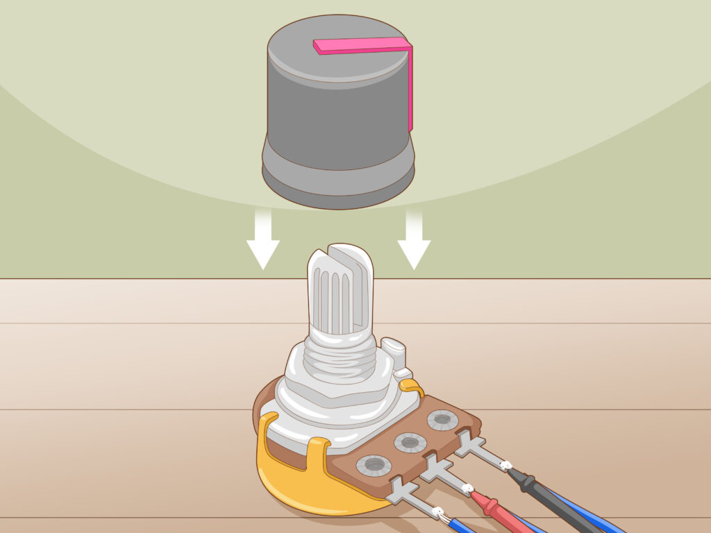
Potentiometer Connection- The potentiometer is a handy small instrument that you practically should understand how to utilize. It is employed in systems a lot to determine the volume of music devices, monitor the brightness of light systems, and other applications. If you are sometimes not familiar with them, it may seem too complex to apply them in a system.
Potentiometers, often known as POTs, are resistors that are used to detect the output signal of electrical instruments such as amplifiers, guitars, and speakers. The Potentiometer is a crucial item in the Industrial Tools Category. Potentiometers are available from a variety of suppliers and companies, as well as various Manufacturers and Distributors, and there are many potentiometers for sale on Linquip.
A full list of potentiometer services is available on the Linquip website, which covers all OEM fleets. Linquip vendors can assist you with this. Please contact Linquip’s Potentiometer Experts to learn more about how to connect with a wide choice of service providers who consistently deliver the highest quality products.
When you see how they are constructed, you can immediately understand how they can be used. Check out the potentiometer definition, wiring principle, and potentiometer connection at this post.
How We Write this Blog Post about Potentiometer Connection
Potentiometer Connection, Working, Circuit Diagram, and Wiring Guide is an important concept that every electrical engineer should know about. It is used to control the voltage in a circuit and can be used in many different applications. Potentiometers are used in audio equipment, lighting systems, and many other electronic devices.
When writing this blog post about Potentiometer Connection, Working, Circuit Diagram, and Wiring Guide, we analyzed various sources and web pages to ensure that we provided accurate information. We consulted with our experts to ensure that we were providing the most up-to-date information possible. We also drew on our previous experiences with potentiometers to provide real-world examples of how they can be used.
What is a Potentiometer?
Resistor, the practical aspect of resistance subject, is one of the most common instruments in the electric circuits. They are typically used to control the current flow by adding resistance to the system. These resistors are present in different sizes and shapes.
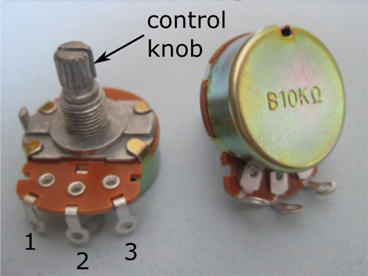
Resistors can be generally categorized into variable and fixed types. As their respective terms present, a variable type has a resistance amount over a defined level, while a fixed format has a single constant value of resistance. Beyond the several Non-linear and linear variable resistors present in the market, the most usual type is the Potentiometer. This post provides the working principle, wiring guide, and potentiometer connection. Therefore, let’s get started.
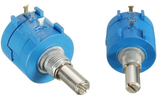
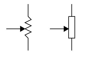
Potentiometers, or POTs, are a form of resistors employed to detect the output signal of electronic instruments, like an amplifier, guitar, or speaker. They have a particular shaft on top that operates like a knob; when the operator rotates that shaft, it changes the resistance value of the instrument. This variation in resistance value is employed to regulate the electrical signal parameters including the gain, volume, or power. A potentiometer is shown by one of the two symbols in a circuit diagram:
How does a Potentiometer Work?
As discussed before, a potentiometer has three sections introduced as terminals. When they are attached to a diagram, the two constant terminals are joined to the end sections of the resistive parts whereas the third one is joined with the wiper.
In the circuit schematic presented below, the terminals of the instrument are signed with 1, 2, and 3. The voltage source is attached to terminals 1 and 3, negative lead to terminal 3 while positive one to terminal 1. Terminal 2 is joined with the wiper.
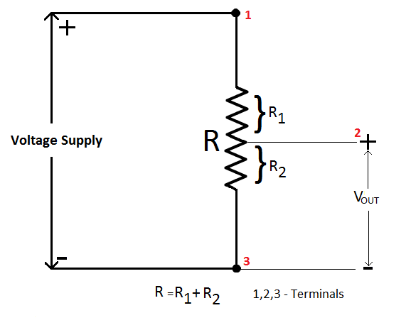
You can see with a closer look at the figure that at the current part of the wiper, there are two particular paths just similar to the resistor is divided into two ones. The resistor that has a longer path will have a higher resistance value since the resistance of a resistor is based on its length.
For example, if we have two resistors, R1 and R2 based on the last figure, the wiper voltage is practically the voltage close to R2. The circuit now operates as a voltage divider, where the output voltage can be evaluated by the next equation:
{ V }_{ out }=\frac { { R }_{ 2 } }{ { R }_{ 1 }+{ R }_{ 2 } } V\quad where\quad V=Supply\quad Voltage
So, if you want to modify the output voltage, you can only modify the amount of R2, by moving the wiper near terminal 3. When the wiper is located at terminal 1, R1 is zero and the voltage within the wiper is equal to the voltage source. In addition, when the wiper is placed at terminal 3, the special resistive value for R2 is zero. Visit here to see the working principle of a Potentiometer completely.
Potentiometer Connection and Wiring
How to Wire a Potentiometer?
You’ll require to put the first terminal to the ground, supply the input sign into the third terminal, and finally apply an output sign across the terminal in the center to set a potentiometer connection or adjust a POT wire. To apply this, you will require to combine each wire to the particular terminal. If you have a little experience to operate with soldering devices, knowing how to wire a potentiometer and potentiometer connection is a pretty simple procedure.
What Are The 3 Terminals on A Potentiometer?
A potentiometer is a three-terminal variable resistor that may be adjusted manually. Two of the terminals are attached to the opposing ends of a resistive element, while the third terminal is connected to a wiper that moves across the resistive element. A three-terminal pot is essentially a voltage divider when used with three terminals. As you move the wiper, you boost one resistor in the voltage divider, while reducing the resistance in the other.
Selecting and Preparing a Pot
This part includes four steps in the process of potentiometer connection:
1. You should detect the 3 basic terminals sticking out of the center of the POT. Then, set your POT on a flat plane with the 3 places that stick out in front of the system. These are the main terminals. The first terminal is the ground. Terminal 2 or the middle terminal is the input port of the POT. Terminal 3 or the third terminal is the output signal. The particular shaft on top directs a small ring combined with terminal 2. Turning it can determine how high or low the input is.
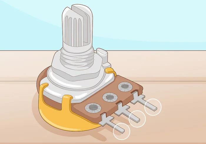
You can suppose a potentiometer as a dimmer instrument. The ground is generally off, terminal 2 is the main switch, and the third terminal is the variable switch that can be turned. A potentiometer is usually used to control an input signal so that it can be regulated. You can sometimes employ a POT to improve an instrument with a greater signal.
2. You must read the resistance values registered on POT to identify what range you can obtain. POTs are hardly employed to monitor signals that are comprised of great volts, but the value of resistance that they support is a considerable matter. The higher the state, the more control you would have about the system. The value printed on the front of the POT determines the highest rate of resistance that the POT can gain. For instance, a 200K POT can supply 200,000 ohms for the circuit at maximum range.
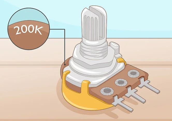
100K type is the most usual potentiometer on the market because it has a common range for audio devices. These values are often printed directly on the surface of POTs. They generally are right close to the shaft on the opposite section of the terminals.
3. First, you should place the POT on a flat plane when the 3 terminals are in front of you. Then, place your POT down on a smooth place near the electronic system. If you want to set the POT in a specific location, you must put the 3 terminals in a particular mode. Finally, remove any panels on the electronic system to use the backside of any output or input sections.
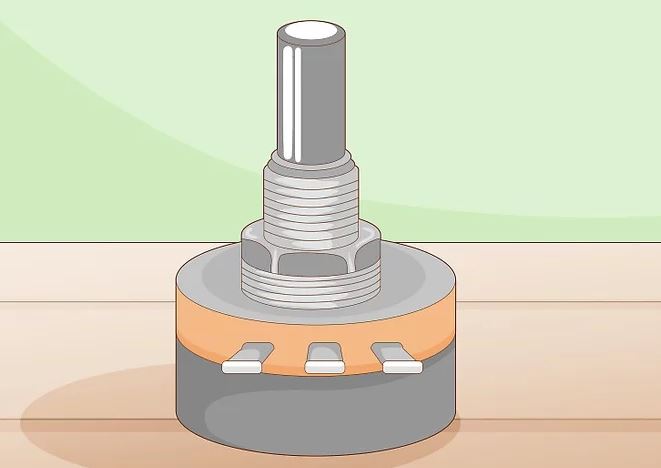
If you’re using a breadboard, install the POT on the upper-most place of rows to be faced with the terminals.
4. You must detect and strip any sections that you want to use in the potentiometer connection. You can employ any type of soldering wire to join the terminals to the system. If you have a setup for installation, control each length of wire from the device to the terminal. By applying wire cutters, prepare any wires to utilize the copper. The size of the cutting is between 1.3 to 2.5 cm of plastic from the top section of each wire.
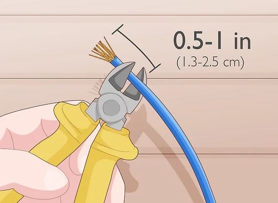
To ensure you can cut the wires cleanly, use your wire stripper properly. You’ll require to solder the wires, so use the soldering flux and iron and place them out on the operation surface. If you’re wiring a particular form of electronic instruments that use specific wires, soldered wires should be double-checked.
Soldering Your Terminals
This section has three steps in the case of the potentiometer connection:
1. First, you should attach a ground wire to the base section from the first terminal on the left. Then, join a little length of wire by covering the exposed section with the soldering flux and iron. When the wire absorbs some flux, drop the wire to combine it with the metal section on terminal one. Press the soldering part to the junction to attach the terminal to the wire. Now, solder the other section to any piece of an exposed metal plane on the electronic circuit.
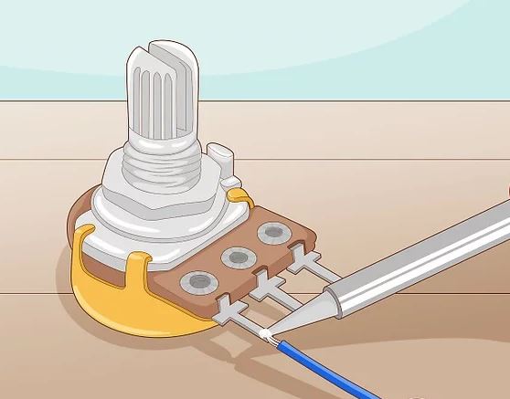
You can utilize the third terminal on the right in particular aims, while this means that you’ll require to rotate the knob clockwise to put the signal down.
2. You should wire the center terminal to the output diagram on your instrument. Then, tin the other length of wire like the last section and join it with the center terminal on the POT. This terminal is the signal entering of the POT, so it requires to be covered properly in the instrument’s output. Finally, solder this wire to the particular connection on the electric device of the output connection.
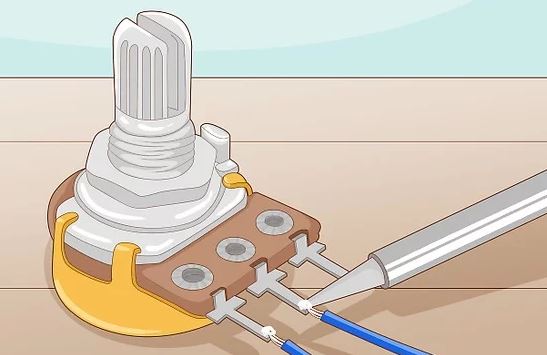
The center terminal is the input of the potentiometer connection. This means that the signal starts with the second terminal, then backs to terminal three. Consequently, the second terminal should be connected to the part that sends the basic signal out of the system. This would mean the wired terminal two is like an output jack on a guitar and similar to the speaker output terminal on an integrated audio amplifier.
3. Finally, you must apply a wire from the third terminal to the input of the device. The third terminal is the output of POT. It is placed where the POT accumulates the information about the device. Then, tin the visible length of the soldered wire and set it directly close to the terminal. Warm it with the soldering pen and combine it with the wire of the input port. Finally, solder this wire straightly to finish the potentiometer connection.
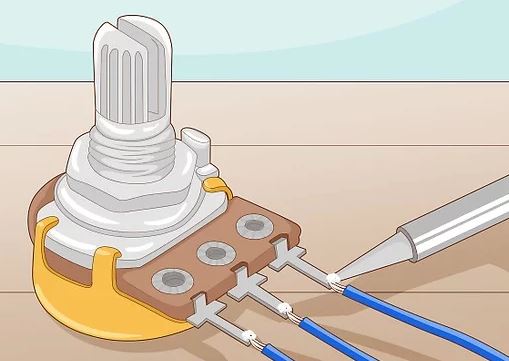
Terminal 3 is the place of moving the signal out of the pot, which means that it should be wired to the place where the signal is sent. This would mean wired terminal 3 is the input jack on a guitar and is the input channel on an audio amplifier.
Using Your Potentiometer
The final section of the potentiometer connection has three steps explained below:
1. You should check the potentiometer connection to make sure that it is operating properly with a voltmeter. Then, attach the terminals of the voltmeter to the output and input terminals of the POT. Turn on the voltmeter and check the signal. Turn the knob of POT to regulate the signal. If the signal value on the voltmeter increases and reduces when you rotate the knob, the potentiometer connection is done appropriately.
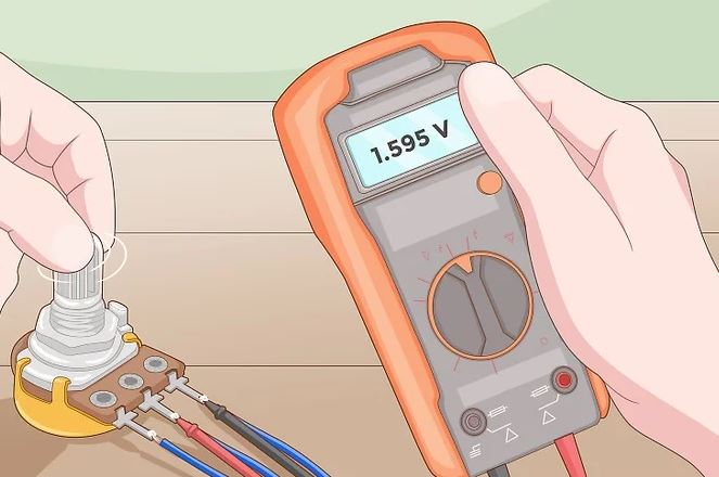
If the voltmeter sends a signal but the device doesn’t operate when you rotate the knob, so there’s a problem in the soldered wire of the potentiometer connections.
2. You must control the signal on your system by rotating the shaft. Turn on the electric system and check the signal of the POT by hitting a guitar note, playing some music, or testing a light system. Then, circulate the shaft in the opposite direction to test the other parts of the system.
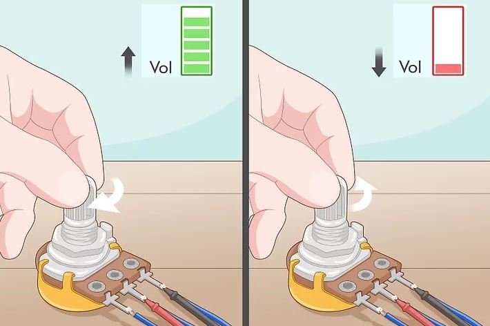
Now, you can employ your POT to vary the value of resistance to control the signal.
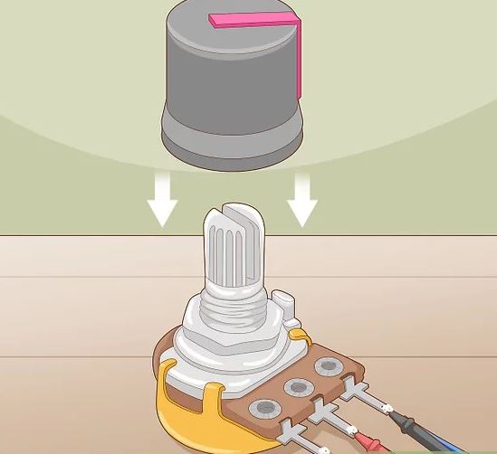
3. Finally, you must add a knob to use on the potentiometer. The potentiometer can be installed with the shaft bare and exposed. But if you want to improve the potential of the potentiometer, you always need a knob. There are various types of knobs in the market constructed to rotate the shaft of a POT and make them more suitable.
FAQs about Potentiometer Connection, Working, Circuit Diagram, & Wiring Guide
How many circuit connections to a potentiometer are needed?
A potentiometer is a three-terminal variable resistor that may be manually adjusted. A resistive element’s opposing ends are linked to two of the terminals, and a sliding contact known as a wiper that moves over the resistive element is attached to the third terminal.
Why we need to include a potentiometer in the circuit?
They aid in producing a variable voltage from a source of fixed voltage and are used to precisely measure voltage. Because they are passive devices, they don’t require a power source or extra circuits to operate.
What do we need to consider when using the potentiometer?
Setting the potentiometer shaft approximately halfway through its journey, then measuring the resistance across each half from the wiper to the end terminal, is the best approach to establishing the kind or law of a certain potentiometer. It is a linear potentiometer if the resistance in each half is about equal.
Does potentiometer affect voltage or current?
Variable resistors include rheostats, trimmers, and potentiometers. By adjusting the voltage between their wiper terminal and two ends, potentiometers and trimmers may produce a variable voltage. The quantity of current may be adjusted using rheostats.
What causes a potentiometer to fail?
Potentiometers can malfunction for a number of reasons, but by far the most of them involve the sliding contact, or more precisely, the point where the electrical contact and track meet. Foreign materials and vibration are the two primary causes of these failures.
Download Potentiometer Connection, Working, Circuit Diagram, & Wiring Guide PDF
You can download this article as a PDF so that you can access it whenever you like.
Potentiometer Connection, Working, Circuit Diagram, & Wiring Guide
Watch Videos about Potentiometer Connection, Working, Circuit Diagram, & Wiring Guide
For more information about Potentiometer Connection, Working, Circuit Diagram, & Wiring Guide, watch this video.
Buy Equipment or Ask for a Service
By using Linquip RFQ Service, you can expect to receive quotations from various suppliers across multiple industries and regions.
Click Here to Request a Quotation From Suppliers and Service Providers
Read More In Linquip
- What is Potentiometer? The Ultimate Guide to Knowing Potentiometers And Their Construction
- Difference Between Potentiometer and Voltmeter
- What is the Difference Between Potentiometer and Rheostat?
- Ultimate Guide: What Is Linear Potentiometer
- What is Rotary Potentiometer? What It Does for Us
- What Is a Digital Potentiometer? An Explanation of the Working Principle and Advantages
- Potentiometer Connection, Working, Circuit Diagram, & Wiring Guide
- What is the Difference Between Potentiometer and Rheostat?
- Types of Potentiometers: The Ultimate Guide to Learning About Different POT Types
- What is Potentiometer? The Ultimate Guide to Knowing Potentiometers And Their Construction

