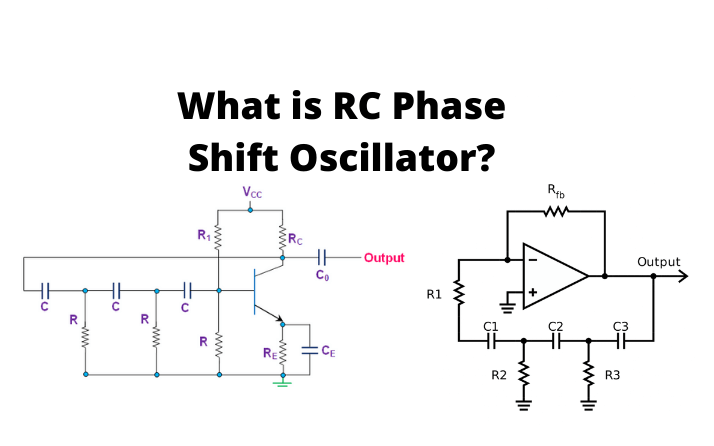
A Phase Shift Oscillator is an electronic type of oscillator circuit that generates wave output in sine format. It can either be modeled by employing an Op-amp or a transistor as an inverting amplifier. A phase shift oscillator is generally utilized as audio oscillator. A 180-degree phase shift is produced in the RC phase shift oscillator by employing the RC arrangement and another 180-degree is produced by the op-amp, so the final wave is configured by 360 degrees. Before we begin to discuss the RC types of phase shift oscillator, Let’s understand what phase and phase shift is.
What is Phase and Phase Shift?
A phase is a full period of a sinusoidal cycle wave in a 360o condition. A complete period is introduced as the interval needed for the wave format to recover its initial value of arbitrary. The phase is known as a particular position on this format of the wave cycle. If we visit the sinusoidal form of the wave, we can simply detect the phase.
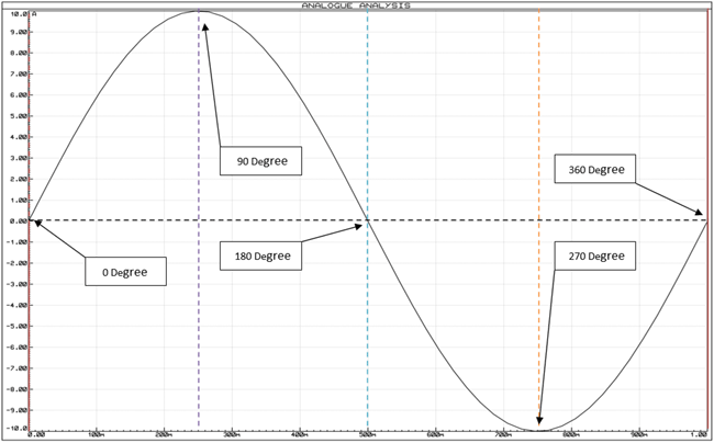
In the previous diagram, a complete form of the wave cycle is presented. The initial point of the start of the sinusoidal wave is 0o in-phase and if we can determine each negative and positive peak and 0 sections, we will find 90, 180, 270, and 360-degree phases. So, when a sinusoidal wave begins, it is operated based on the 0-degree reference. And we introduce it as the phase shift differential according to the 0-degree reference. We can specify how a shifted phase of the sinusoidal wave look-alike by using the next image.
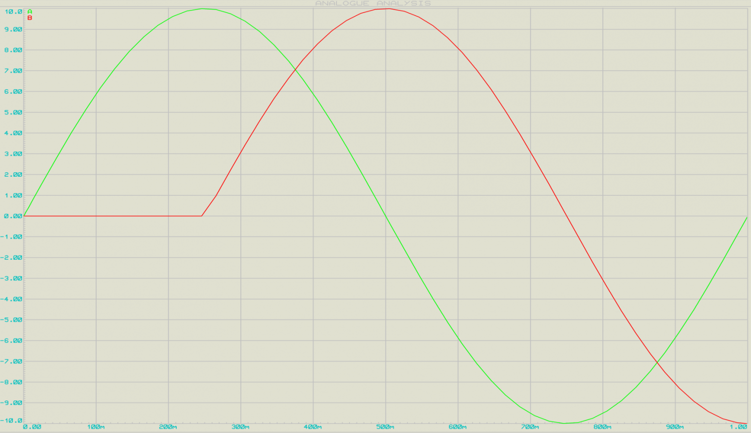
In this diagram, there are two different AC sinusoidal waves illustrated, the basic Green Sinusoidal form is 360o in phase but the red one is 90o phase rotated out of the first signal’s phase. This phase shifting can be applied by employing a simple RC configuration.
What is the RC Phase Shift Oscillator?
A simple schematic of the RC phase shift oscillator presents a minimum phase shift close to 60 degree.
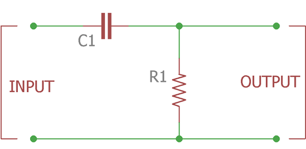
The previous circuit is presented to show a single-pole phase shift in RC arrangement or ladder diagram which alternates the phase of the input signal to output similar to or less than 60o.
The phase shift of the output signal of the RC diagram must be 90 degrees in the ideal form, but actually, it is approximately 60o in practical condition, as the capacitor is not perfect. The equations for evaluating the phase angle of the RC configuration are presented below:
{X}_{C}=\frac{1}{2\pi fC}
Z=\sqrt{{R}^{2}+{X}_{C}^{2}}
\Phi ={tan}^{-1}\frac{{X}_{C}}{R}
R is the resistor and Xc is the reactance value of the capacitor used in the RC circuit. If we change the RC arrangement, we will obtain a 180-degree phase shift oscillator. Now to construct the oscillation and sine form of output, we require an active section, either Op-amp or Transistor in the inverting circuit. If you want to explore more about the RC types of Phase Shift oscillators, follow this link.
Why use Op-amp for an RC Phase Shift Oscillator instead of a Transistor?
There are some limitations to use transistors for designing the RC Phase Shift Oscillator including:
- They are only reliable for low frequencies.
- RC phase shift oscillator needs extra circuitry to provide the amplitude of the waveform by using transistors.
- The precision of frequency is not ideal and it is not suitable for a noisy environment.
- They include adverse loading problems according to the cascade arrangement influence on the second pole’s input impedance which modifies the resistance value and properties of the filter of the basic pole.
- Using the attenuation within the resistor and capacitor increases the loss in each section and the total amount of loss is approximately 1/29th of the input wave. As the diagram removes the 1/29th of the input, we should recover the loss by other methods.
RC Phase Shift Oscillator using Op-Amp
If we utilize an op-amp for RC type of phase shift oscillator, it operates as an amplifier for inverting. At first, the input wave is transferred into the RC configuration, making a 180-degree phase shift oscillator. And, this output signal of RC is supplied by the inverting terminal using op-amp.
Now, as we understand that using op-amp can generate a 180-degree of shifted phase when operates as an amplifier. So, we obtain a 360-degree phase shift oscillator in the output sine form. This RC type of phase shift oscillator employing op-amp supplies a constant frequency even under the modifying load states.
Components Required
Some components are required to design a simple circuit for RC phase shift oscillator explained below:
Resistors including 4.7k, 100k, and 10k
Op-Amp IC Model: LM741
Oscilloscope
Capacitors including 100pF, and 10µF
Circuit Diagram of RC Phase Shift Oscillator using Op-Amp
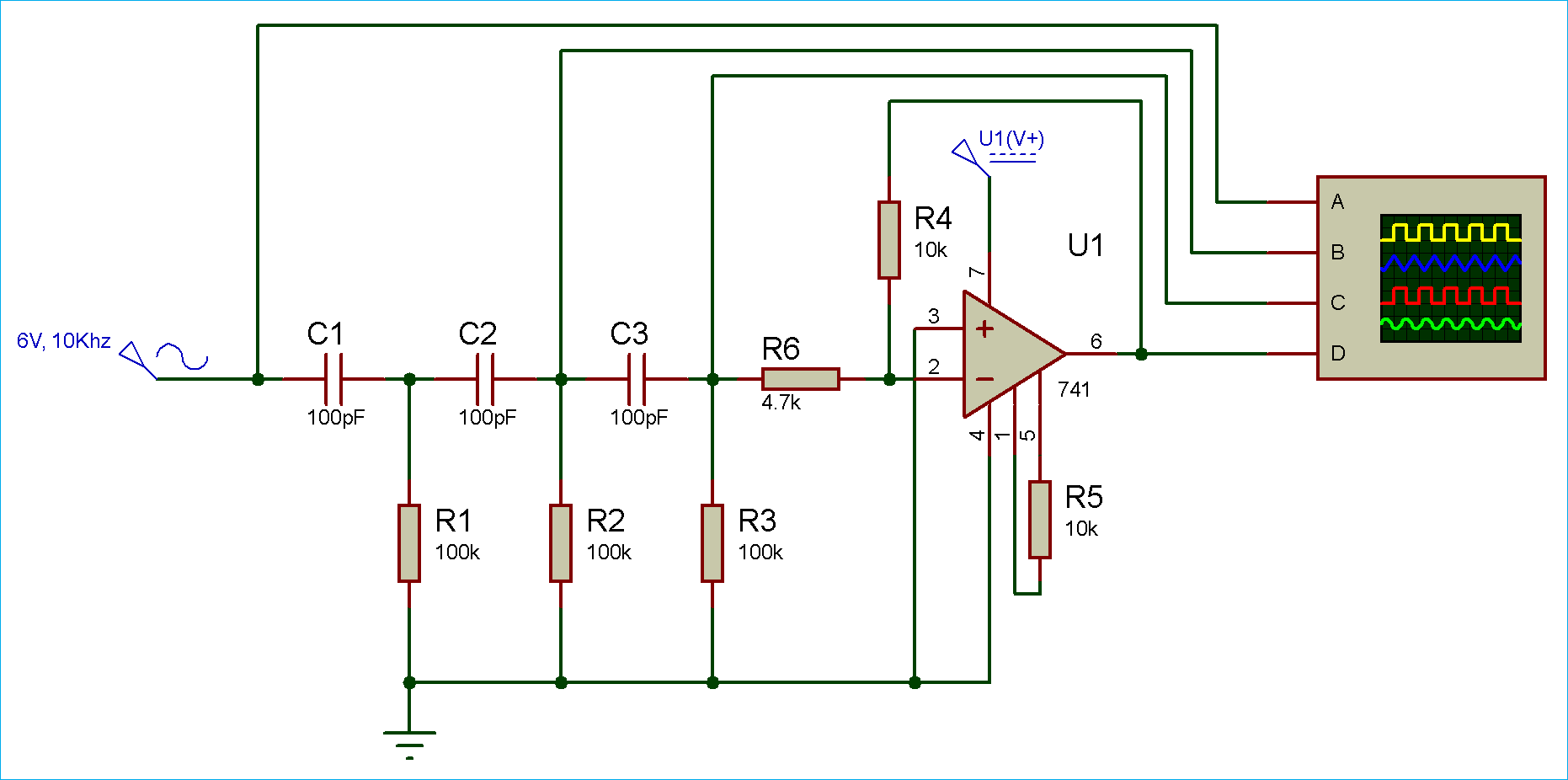
Simulation of RC Phase Shift Oscillator using Op-Amp
RC phase shift oscillator presents a precise sine form of output. As you can visit in the simulation diagram, we should install the probe of the oscilloscope on the four sections of the system.

Here, the feedback arrangement is presenting a phase shift of 180o. We are obtaining a 60-degree shift from each section of the RC circuit. And, the finalized 180-degree phase shift is produced by the op-amp in the inverting network.
For evaluating the frequency of oscillation, we use the next equation:
F=\frac{1}{2\pi RC\sqrt{2}N}
Apart from producing the sine function output, they are also utilized to generate considerable monitoring on the phase-shifting procedure. Other benefits of a phase shift oscillator include Sine Wave Inverter, Audio oscillators, GPS units, Voice Synthesis, and Musical Instruments.
The disadvantage of the RC type of phase shift oscillator employing op-amp is that it cannot be applied for applications with the high-frequency requirement. Because if the frequency is too great, the capacitor’s reactance value is very small and it will operate as a short circuit.
Further, it should be considered that the frequency of the RC types of phase shift oscillator can be changed by modifying either the capacitors or the resistors. Although, the resistors are generally maintained constant while the capacitors are changed.
In addition, by comparing the RC type of phase-shift oscillator with LC oscillators, we can say that the former employed a great number of circuit instruments than the latter one. As a result, the output signal generated by the RC oscillators can deviate more from the calculated value than the actual value of LC oscillators. Nonetheless, they are utilized as local oscillators for synchronous devices, musical systems, and audio-frequency generators. Visit here to see the fundamental operation of the RC phase shift oscillator completely.
Construction of Phase Shift Oscillator
The phase shift oscillator diagram includes a single transistor amplifier component and the RC phase shift configuration. The phase shift configuration in this system has three RC parts. At the resonant frequency (fo), the phase in any RC section has a 60o shift, so the final phase shift generated by the RC system is 180o. The following diagram presents the arrangement of instruments in an RC phase shift oscillator.
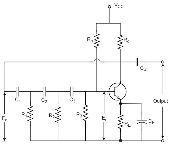
The frequency of oscillations in this circuit is obtained by
{f}_{o}=\frac{1}{2\pi RC\sqrt{6}}
Where
{R}_{1}={R}_{2}={R}_{3}={R}
{C}_{1}={C}_{2}={C}_{3}={C}
Operation of Phase Shift Oscillator
The circuit in the ON-switched state oscillates at the resonant frequency or fo. The output voltage of the amplifier (Eo) is supplied by the RC feedback arrangement. This configuration generates a 180-degree phase shift and another voltage (Ei) is provided near its output. This voltage is operated by the transistor amplifier. So, the feedback rate will be
m=\frac{{E}_{i}}{{E}_{o}}
The feedback is in the correct state, while the transistor amplifier, which is in CE arrangement, generates a 180o shift. The phase shift made by the network and the transistor is used to create a phase shift oscillator around the total loop which is exactly 360o.
Advantages of Phase Shift Oscillator
The advantages of the RC type of phase shift oscillator are mentioned below:
- It does not need any inductor or transformer.
- It can be employed to generate very low frequencies.
- The circuit presents perfect frequency stability.
Disadvantages of Phase Shift Oscillator
The disadvantages of the RC type of phase shift oscillator are as the following:
- The starting section of the oscillation is too problematic since the feedback is very small.
- The generated output is too low.
Buy Equipment or Ask for a Service
By using Linquip RFQ Service, you can expect to receive quotations from various suppliers across multiple industries and regions.
Click Here to Request a Quotation From Suppliers and Service Providers
Read More on Linquip

