Counter Flow Heat Exchangers are called the exchangers, which have the opposite fluid direction for the flows and are categorized based on the flow arrangement. Plate, shell and tube, double-pipe, one phase, and multi-phase can be counter flow exchanger.
Find all the information you need about counter flow heat exchangers on Linquip’s website. Linquip’s heat exchanger experts are standing by to assist you with any questions you may have. Start by reading Linquip’s article entitled, “What Is Counter Flow Heat Exchanger?“.
To access all the features offered, you can also register as a Linquip Expert. What do you think about Guest Posting on the Linquip platform? Linquip gives you the option to submit your content as a guest.
⇒ View a List of Heat Exchanger for Sale and Their Suppliers ⇐
What are the Types of Heat Exchangers?
Typically there are two primary classifications for heat exchangers based on the flow arrangement: parallel flow and counter flow heat exchangers, known as inline and crossflow, respectively.
Inline
In this type of exchanger, hot and cold fluids flow parallel to each other. If they move in the same direction, they are called parallel or co-current, and if they move opposite each other, they are named counter-current counter flow heat exchangers.
Counter flow heat exchangers are more efficient than parallel exchangers, and it is all because of a uniform temperature difference between fluids over the whole exchanger and fluid paths.
Crossflow
In crossflow heat exchangers, the fluid in the hot and cold sections moves perpendicular to each other. This type is more efficient than counter flow heat exchangers, and all the heat exchanger can be in a box. Logarithmic mean temperature difference (LMTD) in this type is larger than inline type.
What is a Counter Flow Heat Exchanger?
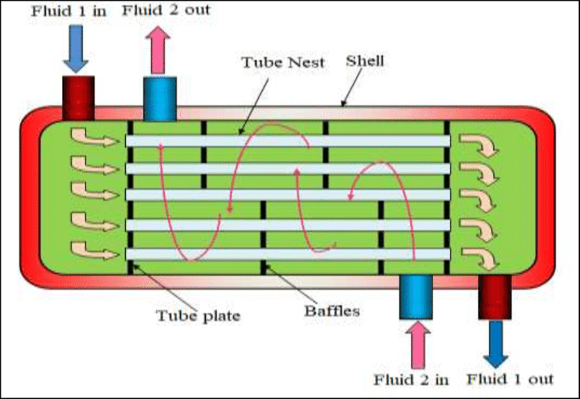
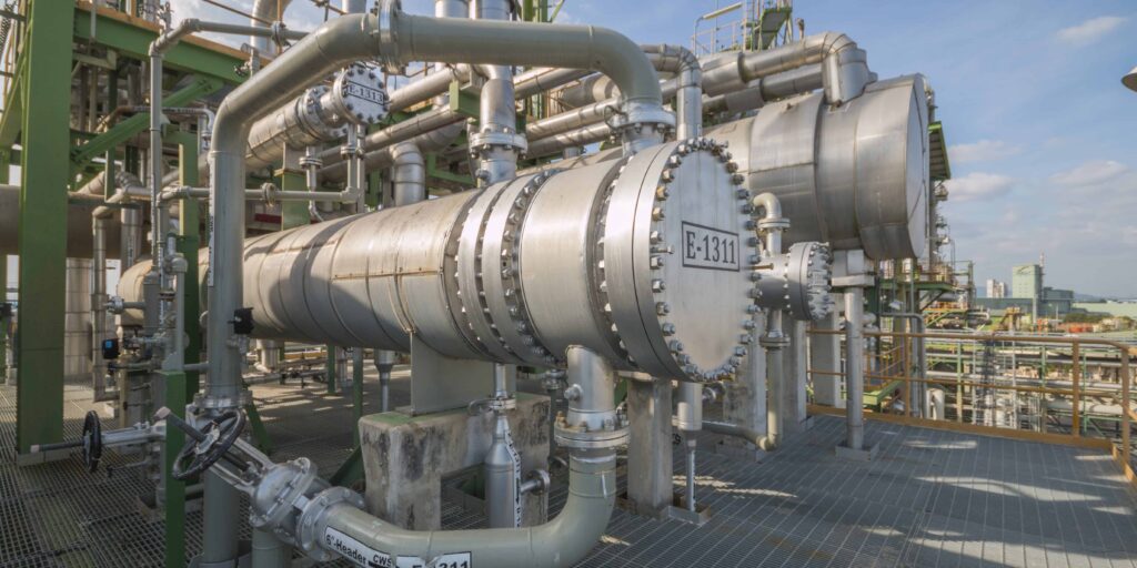
Counter flow heat exchangers use flows in the opposite direction of each other. Shell and tube, and double pipes heat exchangers are examples of common exchangers using counter flow configurations. The best design for shell and tube and double-pipe exchanger is counter flow configuration, and the heat transfer between the fluid is the maximum. In counter flow, the efficiency is higher than the parallel, and temperature in the cooling fluid outlet can exceed the warmer fluid inlet temperature.
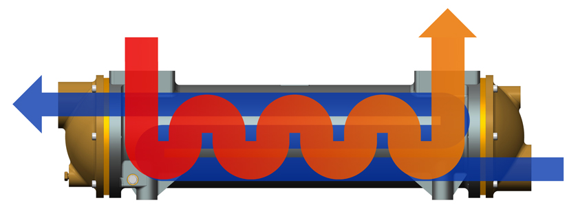
In the figure below, we can see the position of inlets and outlets. As it is illustrated in the counter flow heat exchanger, the fluids flow in the opposite direction, and at the heads, there is a maximum temperature difference between them. We have an inlet for hot fluid and the exit pipes of cold fluid at the left head, while cold fluid inlets and the hot fluid outlet are on the right head. For understanding what the counter flow is, we should know the differences between counter flow and parallel flow.

What are the Differences Between the Parallel and Counter Flow Heat Exchangers
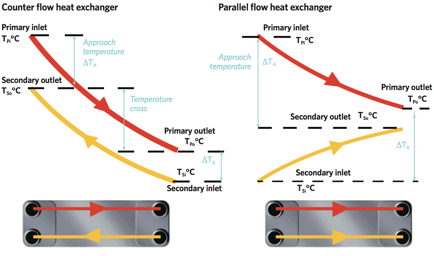
Parallel and counter flow heat exchangers are different in the flow direction and the heat transfer diagrams. In parallel exchangers, both of the inlets are placed on the same side, and we have all the outlets on the other side. The maximum temperature difference is happening in the inlet, and it decreases to reach the minimum at the outlets. It is totally the inverse type compared to the counter flow. Inlet and outlet position and temperature diagram for the parallel and counter flow heat exchanger is presented in the figure below:

As discussed before, the base of all heat exchangers is simple, and it is the transfer of heat from the hot fluid to the cooler ones and exchange energy between them. The surface of plates, pipes, or whatever separates the fluids in a heat exchanger has a great impact on the heat transfer, and by increasing it, we can reach a high rate of heat transfer for heavy-duty applications.
The design of the size and type of the heat exchanger depends on the amount of heat transfer and the output temperature of the fluids. If the purpose of the device is cooling, the hot fluid output temperature is important, and if the purpose is heating, the cold fluid output temperature is critical.
Advantages and Disadvantages of Parallel Over Counter Flow Heat Exchanger
We use parallel flow in applications, in which the flows at the outlet have near temperatures together, and we want to have the same temperatures. By looking at the parallel exchanger diagram, we notice a large temperature difference on one side, which makes large thermal stress on the components. Expansion and contraction in the solid parts can eventually lead to failure. Also, as can be seen, we can’t have a higher temperature in the outlet for the cold fluid compared to the hot fluid, which is the most important disadvantage of the parallel one.
Counter flow heat exchangers have three noticeable advantages over parallel exchangers. As it is shown in the diagram, we have a uniform temperature difference along the heat transfer area that minimizes the thermal stress in the system. The second one is the output temperature, which can have a higher value compared to the hot fluid. The final benefit of this type is uniform heat transfer between the fluids and larger LMTD (LMTD will be discussed in the next section).
Heat Transfer in Parallel and Counter Flow Heat Exchanger
Whether we use parallel or counter flow heat exchanger, we have both convection and conduction. The heat transfer along the exchanger varies, and it is all because of the different temperatures at each point of view. Heat flows from the hot side to the cold side, and we have convection heat transfer between the fluids and the solid on both sides, while the heat transfer process is conduction in the solid part.

As can be seen in the figure, the temperature difference in counter flow is greater, and it causes a larger amount of heat transfer in the exchanger. The heat transfer can be calculated by the equation of Q=UA \Delta T_{LM}. it is the same for all the exchangers and the parameters are:
U= Average thermal transmittance from one fluid to the other one (W·m-2·K-1)
A= Heat transfer area in the exchanger
\Delta T_{LM} = Logarithm mean temperature difference between fluids.Logarithm mean temperature difference or LMTD can be calculated as below:
\Delta T_{LM}=\frac{\Delta T_{A}-\Delta T_{B}}{Ln(\frac{\Delta T_{A}}{\Delta T_{B}})}
A small change in the fluid temperatures in the inlets lead to a large LMTD in the exchanger, for example, for a 70°C and 80°C temperature of the inlet and the outlet in one flow and a 40°C and 44°C for the other flow, we have LMTD of 6.55°C. By an increase of 2°C in the first flow, we have an 11 percent increase in the LMTD, which is a significant amount.
\Delta T_{LM}=\frac{\Delta T_{A}-\Delta T_{B}}{Ln(\frac{\Delta T_{A}}{\Delta T_{B}})}=
\frac{10-4}{2.303-1.386}=6.55
We can calculate the overall sensible heat transfer for a single-phase flow as:
Q=mC_{p}\Delta T
where:
m = Mass flow rate for the liquid flow (kg·s-1)
Cp = Specific heat capacity of the liquid fluid (kJ·kg-1·K-1)
ΔT = Difference between temperatures in the outlet and the inlet of the liquid flow (K)
If we have 100 percent efficiency in the system, this sensible heat transfer for both flows should be the same.
The thermal transmittance is a function of the plate material and its thermal resistance, heat transfer coefficient of the surface on the cold and hot flow. Usually, we have turbulent flow in the system, and as a result, the heat transfer coefficient of the surface is large, which is good for increasing the heat transfer rate.
By creating turbulent flow, we destroy boundary layers and help the heat transfer rate, but it causes a larger pressure drop. Turbulent flow helps to have less deposition of unwanted materials such as algae, scale, insoluble salts, and suspended solids on the surfaces. Also, for decreasing the resistance of the materials in the solid part, it is preferred to have a thin barrier. Stainless steel has a low thermal resistance and also have good resistance against corrosive fluids.
The basic performance of the exchanger can be calculated by knowing the size of the exchanger and flowing fluids:
\eta =\frac{U.A}{m.C_{p}}
Download Counter Flow Heat Exchangers PDF
You can download this article as a PDF file if you would like to read it whenever you like.
Buy Equipment or Ask for a Service
By using Linquip RFQ Service, you can expect to receive quotations from various suppliers across multiple industries and regions.
Click Here to Request a Quotation From Suppliers and Service Providers
Read More on Linquip
- Coil Heat Exchanger: All Essentials You Need to Know
- What is Cross Flow Heat Exchangers and its Working Principles
- Tubular Heat Exchangers: All Essentials You Need to Know
- Quick Guide On What Is Floating Head Exchanger
- Advanced Guide: What Is Tube In Tube Heat Exchangers
- Heat Exchanger vs. Chiller: Which One is the Best for You?
- Difference Between Heat Exchanger and Condenser: A thorough guide 2022
- Heat Exchanger Efficiency Calculation & Equation
- Tubular Heat Exchangers: Usage & Working Principle
- What is Coil Heat Exchanger? Design Example
- Demystifying Heat Exchanger Sizing: A Comprehensive Guide


