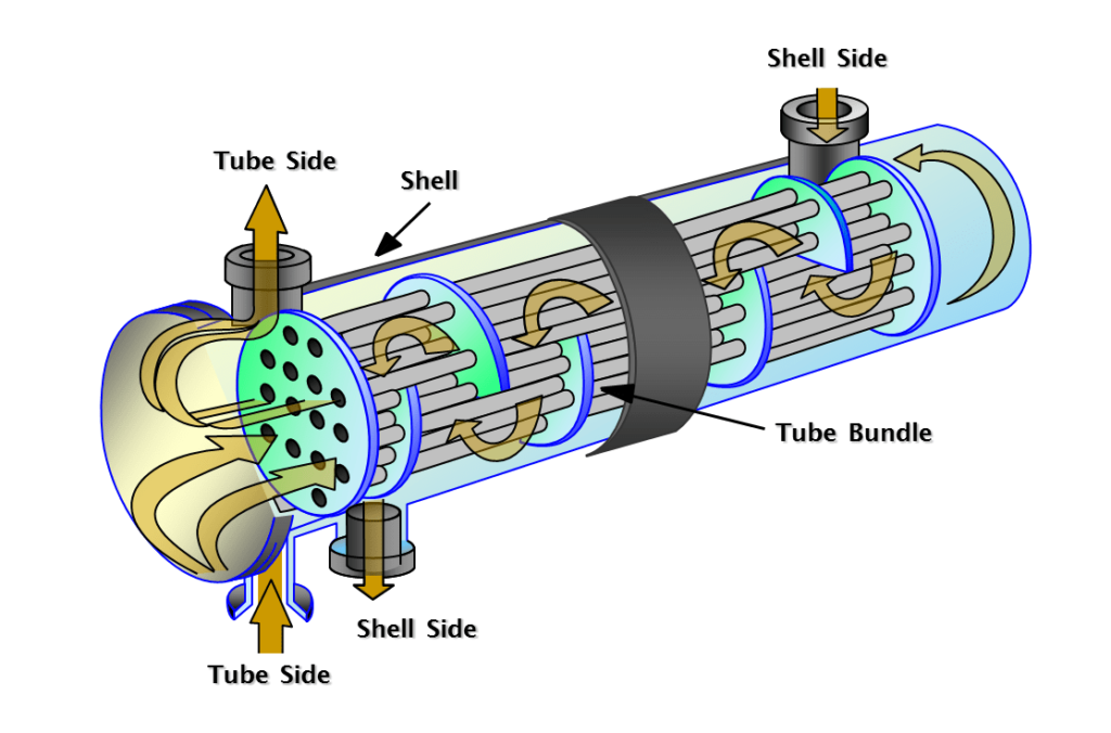
The heat exchanger is an important and common industrial device. Therefore, it is necessary to know the structure and the parts of heat exchanger. These parts can vary in detail depending on the type of heat exchanger and its performance. But the purpose of arranging heat exchanger parts is to form industrial equipment to perform the task of cooling or heating in order to transfer heat.
There are various types of exchangers, and each one has its advantages and disadvantages. Despite all the differences and details, different heat exchangers have the same basic structure. In the following sections, we will introduce the components of heat exchangers and explain their functions. The major heat exchanger parts are depicted in the figure below.
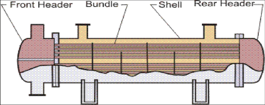
The Heat Exchanger Tubes
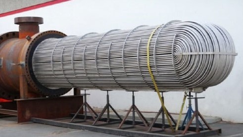
Tubes are the most fundamental part of a heat exchanger to transfer liquids. Tubing is in the form of welded or seamless, but the welded type is more economical than the other one. The tube diameters typically are 5/8 inch, 3/4 inch, or 1 inch. Some tubes have smaller diameters. However, it is better to be avoided because the cleaning is more challenging in this case.
To achieve a lower pressure drop, larger diameters might be used. Some tubes are equipped with supplements known as twisted tapes to enhance heat transfer when working with fluids with laminar flow conditions. All tubes are bundled and kept in a shell or casing.
Tubes of Heat exchangers are manufactured in various types of austenitic or duplex stainless steels, nickel alloys, zirconium, and titanium, which are proper for all heat exchanger types in the applications of heaters and reheaters, coolers, condensers, and evaporators.
The Heat Exchanger Front and Rear Headers
The fluid enters the heat exchanger from the front header. It exits the rear header before re-entering the front header to pass through the tubes several times. The front header is also called the stationary header.
Front Header Types
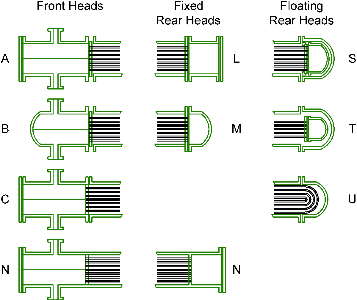
There are different types of front headers, including A-B-C-D-N-Y types. These are fixed types, and their application varies according to the flow pressure, cost, ease of cleaning, and repair. For example, type B is cheaper than type A and is used for higher pressures, but type A is easier to repair. Types C and D are used for pressures above 100 bar. In type N, the tubes can be accessed without disturbing the operation of the system. Y is also the cheapest front header and is installed in a pipeline.
Rear Header Types
There are two available rear headers: fixed and floating.
For standard service, a Fixed rear header including L, M, and N-types are used if there is no high mechanical stress because of differential expansion and the shell side does not need cleaning. When there is a possibility of thermal expansion, a fixed rear header with a bellows is used if the shell side fluid is not dangerous and does not need mechanical cleaning, and the pressure does not surpass 35 bar.
A U-tube rear header is used to overcome the problems with thermal expansion and facilitates cleaning the bundle by removing it.
An S-type header, which is a floating type, is used when thermal expansion must be provided. Also, it is necessary to access both sides of the exchanger for cleaning. Other rear header types are not usual except for exceptional cases. The T-type header is another floating header that is cheaper and simpler to extract the bundle than the S-type. It allows for unrestricted thermal expansion.
In the figure below, you can see the types of front and rear headers.
Transfer Line Exchangers
Transfer line exchangers (TLX) task is to cool very hot gas quickly. Their function is more noticeable in very harsh conditions. TLX design depends on the heat exchanger tubing pattern, but it needs a special design to work efficiently. They join the radiating coil outlets through flange or welded juncture. For the regions exposed to hot gas but not cooled by water, they require internal insulation.
The Air Cooling System of a Heat Exchanger
The system of air cooling in a heat exchanger contains fin fans, condensers, and chillers. The design of fin fans is performed to meet the need of blowing over the hot tubes to keep them cool efficiently. The condenser function is to cool objects until the phase change from a gas to a liquid occurs. Chillers utilize water as their coolant and keep the water temperature low to cool the devices without freezing the water.
Heat exchanger Shell
In shell and tube heat exchangers, one fluid flows inside the tubes, and the other fluid flows inside the shell. The shell is a large pressure vessel inside which the pipe bundles are located. This is the most expensive component among heat exchanger parts. The figure below shows the construction of the heat exchanger consisting of shells and tubes.
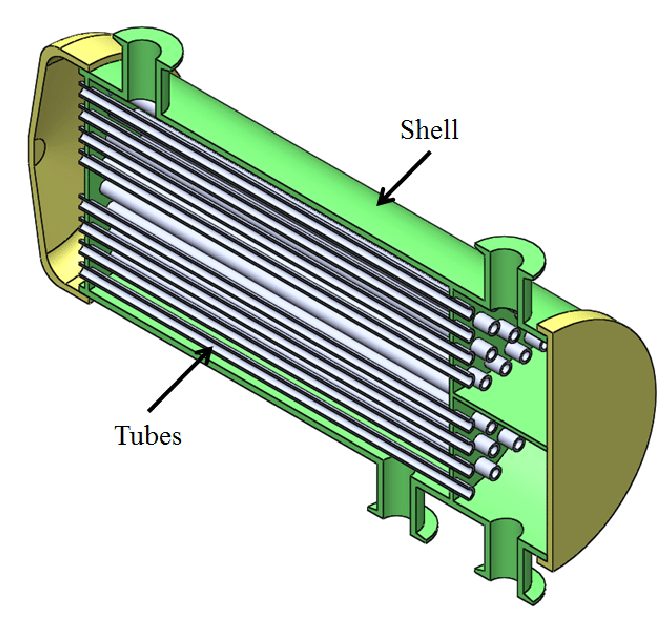
Usually, high-pressure fluid flows into the tubes, and low-pressure fluid flows into the shell. The shell has to be maintained against high pressures by rupture discs or relief valves. The diameter of the shell is dependent on the diameter of the tube bundle. Standard pipes are usually used for shell diameters up to 24 inches. Above this value, the shell is from the rolled plate. Typically shell diameters range from 6 inches to 120 inches.
Heat Exchanger Baffles
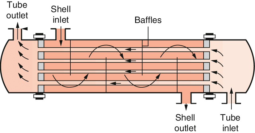
Baffles are mounted on the shell side to supply a higher heat transfer rate, consequently increasing turbulence of the flow. Also, these heat exchanger parts help to support the tubes and reduce problems due to vibration.
Baffles Arrangements
The baffles are installed in different arrangements, including Single Segmental as the most common, Double Segmental, which causes a lower shell side velocity and pressure drop, and Disc and Doughnut. The following figure shows these three arrangements in the order introduced.
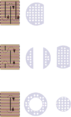
The term baffle pitch is defined as the center-to-center distance between baffles. It can be changed to vary the cross-flow velocity. Practically, the baffle pitch is not usually larger than the inside diameter of the shell or less than 20% of the diameter.
A part of the baffle is removed to enable the fluid to move backward and forward across the tubes. The baffle cut size (also called baffle window) is considered along with the baffle pitch. Baffle cut size depends on the baffle type. However, it is usually 45% for single segmental and 25% for double segmental types.
Baffles Types
There are different types of baffles to suit the use, size, and cost.
- Longitudinal flow baffles are used in the case of a two-pass shell. There are two principal baffle types that supply longitudinal flow: Orifice baffle and Rod baffle, in which the turbulence is produced as the fluid flow crosses the baffle.
- Impingement Baffles are used for maintaining the bundle when the entry velocity is high.
- De-resonating (detuning) baffles are used to decrease tube vibration.
- Single segmental baffles
- Double segmental baffles
- Support/Blanking baffles
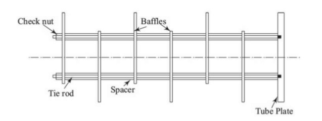
To ensure the spaces between the baffles, spacers are used. They prevent the baffles from sliding due to the force applied by the fluids. The number of spacers depends on their sizes and the diameter of the shell.
Heat Exchanger Tube sheet
The tube sheets help support and isolate the tubes. Tubes are connected to the tube sheet by applying hydraulic pressure or by roller expansion. A tube sheet may be covered by a clad, which assists as a corrosion preventive and insulator.
Heat Exchanger Tie rods
Tie rods are important heat exchanger parts. They are secured to the last baffle in one end and the tube sheet on another end. In the following figure, tie rod location is seen.
Read More on Linquip
- Demystifying Heat Exchanger Sizing: A Comprehensive Guide
- Heat Exchanger Efficiency: Tips for Having an Efficient Heat Exchanging System
- Types of Heat Exchangers: An Introduction to All Essential about Specifications
- Heat Exchanger vs. Chiller: Which one is the best?
- What is Plate Heat Exchanger?
- What is Scraped Surface Heat Exchanger? Find it Where it is used

