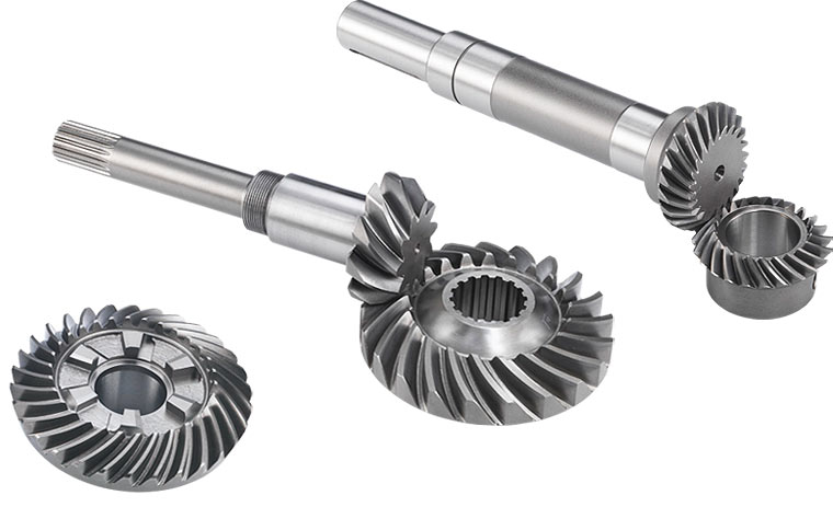
Types of Bevel Gears- There exists a special type of gear introduced as the Bevel Gear. Bevel gears include two main shafts that intersect with their splines modeled as the cones. These types of bevel gears are typically used on shafts and are placed 90 degrees from each other. Types of bevel gears are classified according to the geometry of the total design. But now, we should clearly explain what a bevel gear is.
What is a Bevel Gear?
Bevel gears are instruments whose axes of the two main shafts are cut across and the tooth-bearing sections of the gears themselves are conically modeled. Bevel gears are typically assembled on shafts that are exactly 90 degrees apart but can be produced to perform at other angles as well. The pitch surface of a bevel gear is shaped like a cone.
Two basic concepts in gearing are the pitch angle and pitch surface. The pitch angle of a gear is known as the angle between the axis and the face of the pitch surface. The pitch surface of a gear is the unreal toothless surface that you would have by evaluating the valleys and peaks of the individual teeth. The pitch surface of a common gear is the shape of a cylinder.
The most usual types of bevel gears have pitch angles smaller than 90 degrees and therefore are modeled as the cone. This kind of bevel gear is introduced as the external form since the gear teeth point outward. The pitch plates of meshed external forms are coaxial with the gear shafts; the top points of the two surfaces are at the point of the shaft axes’ intersection.
The application of an actual bevel gear has even greater importance for axle stability than any other spare component. Bevel gears that include pitch angles higher than 90 degrees have teeth that point inward and are introduced as internal bevel gears.
Bevel gears that include pitch angles of precisely 90 degrees have teeth that stand parallel with the axis and mount the points on a crown. That’s why these types of bevel gears are known as crown gears. Visit here to see the different types of bevel gears completely.
Types of Bevel Gears
Bevel gears are categorized in different forms according to their geometry:
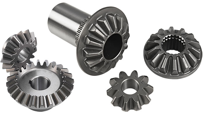
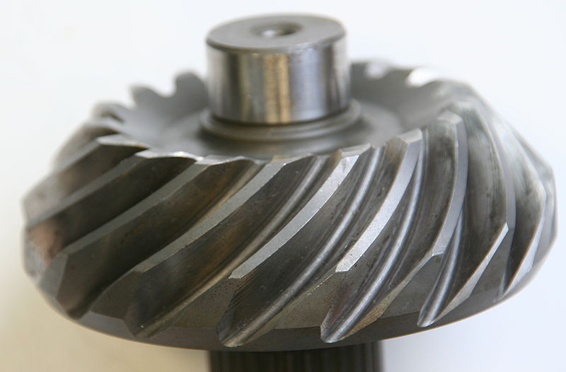
A straight bevel gear includes a conical pitch surface and teeth with straight and tapering towards the apex. Spiral bevel gears include curved teeth at a particular angle, causing tooth contact to be smooth and gradual.
Zerol bevel gears are very similar to a typical bevel gear; while their teeth are curved, the ends section of each tooth is coplanar with the axis, and the middle part of each tooth is circumferentially swept around the gear. Zerol bevel gears can be introduced as a kind of spiral bevel gears, which also have special teeth, but with a zero spiral angle, so the teeth’ ends align with the axis.
Hypoid bevel gears are similar to spiral bevels, but the pitch surfaces are not conical and hyperbolic. The pinion can be set below or above the gear center, thus permitting greater pinion diameter, smoother mesh, and longer life. If the beveled plate is constructed parallel with the rotation axis, this setup resembles a worm drive. Hypoid gears were broadly employed in automobile rear axles.
Mitre Gears
Mitre gears are a particular case of bevel gears that have the same number of teeth. The shafts are located at right angles arrangement from each other, and the gears have setting pitch surfaces and angles, with a conically-form pitch surface. Mitre gears are beneficial for transforming rotational movement at a 90-degree angle with a 1:1 ratio.
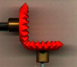
The Geometry of Different Types of Bevel Gears
A double-helical form of bevel gear was constructed by Citroën in 1927 for the Miřejovice water power plant. The cylindrical gear tooth shape corresponds to a twisty form (i.e. a triangle wave installed on the circle circumference), while the bevel gear tooth profile is an octoid (i.e., a triangle wave installed on the standard path of an edge of a sphere).
All usual bevel gear manufacturers (such as Heidenreich & Harbeck, Gleason, WMW Modul, and Klingelnberg) generate bevel gears with an optional tooth shape. It is important to consider that for 5-axis assembled bevel gear sets, it is essential to select the same calculation/layout, including the conventional production method.
Simplified estimated bevel gears on the foundation of an equivalent cylindrical gear in a standard section with an involute tooth shape, demonstrate a deviant tooth shape with decreased tooth strength by 45% with offset and 10-28% without offset. In addition, those “involute bevel gear configurations” cause more noise.
List of Drawing Symbols in Different Types of Bevel Gears
Teeth
There are two aspects regarding the shape of the tooth. First is the cross-sectional profile of the individual tooth, and the second is the curve or line on which the tooth is installed on the gear face; in other words, the curve or line along which the cross-sectional shape is set to forms the actual three-dimensional form of the tooth. The first result of both the cross-sectional shape and the tooth curve or line is the smoothness of the gear’s performance. Some result in a smoother gear operation than others.
Tooth Line
The teeth on bevel gears can be categorized into straight, spiral, or Zerol forms.
Straight Tooth Lines
The teeth are straight and parallel to the basic section of the cone in straight bevel gears. This is the easiest type of bevel gear. It mounts a spur gear, just conical rather than cylindrical. The gears in several applications are straight bevel gears. In the configurations of straight type, when each tooth performs, it influences the corresponding tooth and easily revises the gear teeth which can solve the basic problem.
Spiral Tooth Lines
Spiral bevel gears have their particular teeth created along spiral lines. They are types alike to the cylindrical form of helical systems in that the teeth are formed; although, with spiral gears, the teeth are also curved.
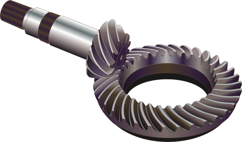
The main benefit of the spiral tooth over the straight form is that they engage more moderately. The touching between the teeth begins at one section of the gear and then spreads within the total tooth. This results in a less abrupt transmission of power when a new pair of teeth is used.
The abrupt tooth engagement causes noise with the straight bevel gears, particularly at high speeds, and results in stress on the teeth, which makes them ineffectual to take strong forces at high velocities without breaking. For these reasons, straight forms are commonly restricted to use at linear speeds less than 1000 feet/min; or, for traditional gears, under 1000 rpm.
Zerol Tooth Lines
Zerol bevel gears are a transitional form between spiral and straight bevel gears. Their teeth have a certain curved shape but are not angled. Zerol bevel gearbox is modeled with the intent of duplicating the features of a straight bevel gear, but they are created using a spiral bevel-cutting procedure.
Manufacturing of Different Types of Bevel Gears
Materials Used in Gear Manufacturing Process
Different materials employed for gears contain a wide variety of cast irons, non-metallic materials, and non-ferrous materials. Choosing the gear material is based on:
- Method of manufacture
- Type of work
- Required dimensions and weight of the drive
- Peripheral speed
- Allowable stress
- Degree of accuracy required
- Shock resistance
Some substances chosen include:
- Cast iron, which is commonly based on its good wearing features, excellent machinability, and ease of generating complicated forms by the casting method. It is appropriate where large gears of complicated forms are required.
- Steel, which is strong enough and extremely resistant to wear by abrasion.
- Cast steel, which is utilized where stress on the gear is great enough, and it is problematic to fabricate the gears.
- Plain carbon steels, which discover application for industrial systems where great toughness combined with large strength.
- Alloy steels, which are employed where great tooth strength and small tooth wear are needed.
- Aluminum, which is used where small inertia of rotating mass is asked.
- Gears made of non–metallic substances give a noiseless performance at high peripheral velocities.
Main Applications of Types of Bevel Gears
The bevel gear has many different applications such as marine applications, locomotives, printing presses, automobiles, cooling towers, steel plants, power plants, railway track inspection machines, etc.
For examples, see the following cases:
- Bevel gears are employed in differential drives, which can transfer energy to two axles rotating at different velocities, such as those on a cornering automobile.
- Bevel gears are used as the basic function for a hand drill. As the handle of the drill is rotated in a vertical form, the bevel gears modify the spinning of the chuck to a horizontal motion. The bevel gears in this system have the extra benefit to improve the rotation velocity of the chuck, and this makes it feasible to drill a range of substances.
- The gears in a bevel gear planer allow for minor regulation during assembly and permit some displacement based on the deflection under operating powers without concentrating the force on the end part of the tooth.
- Spiral bevel gears are essential parts of rotorcraft drive arrangements. These parts are needed to perform at high loads, high speeds, and several load cycles. In this case, spiral bevel gears are employed to revise the shaft from the horizontal form of a gas turbine to the vertical output. Bevel gears are also employed as velocity reducers.
Conclusion
As can be seen, bevel gears come in various models based on the geometry of the gear plane and the splines. The straight bevel gear is identical to the zero bevel gear except for the shape of the spline or teeth. The hypoid bevel gear is identical to the bevel gear except for the pitch surface of the latter. The adaptation of the geometric form is detected by what the bevel gear is required for, and what its performance should be within a machine.
The Ultimate Guide to the Types of Gearbox
Buy Equipment or Ask for a Service
By using Linquip RFQ Service, you can expect to receive quotations from various suppliers across multiple industries and regions.
Click Here to Request a Quotation From Suppliers and Service Providers
Read More on Linquip
- The Ultimate Guide to the Types of Gearbox
- Gearbox Components and Parts: Everything You Need to Know
- Industrial Gearbox A Comprehensive Review on Features, Types, and its Usability
- What is Gear Shaft?
- What is a Bevel Gear and How Does it Work?
- What is a Helical Gearbox?
- Differences Between Worm and Helical Gear
- Types of Induction Motor: A Concise and Useful Guild
- All About DC Motor Types and Their Applications
- Types of Heat Exchangers: An Introduction to All Essential Specifications
- What is a Worm Gearbox?
- What is Planetary Gearbox and How Does it Work?
- The difference between gearbox and transmission

