Types of Electric Circuit- Closed circuits, open circuits, short circuits, series circuits, and parallel circuits are the five main types of electric circuits. Let us learn and comprehend using definitions, examples, and symbols in depth. The term “electric network” refers to a collection of distinct electric elements or components that are linked in some way. A complex network is a circuit that incorporates several electrical elements such as resistors, capacitors, inductors, current sources, and voltage sources (both AC and DC). Simple ohm’s law or Kirchhoff’s laws are insufficient to address these types of networks. To put it another way, we solve these circuits using specialized techniques like Norton’s Theorem, Thevenin’s Theorem, Superposition Theorem, etc.
What is an Electric Circuit?
An electrical circuit is a network of components used for energy storage, transmission, and conversion. One or more sources supply energy to a circuit, and one or more sinks remove it. Energy is converted from thermal, chemical, electromagnetic, or mechanical form to electrical form in the sources; the process is reversed in the sinks. Energy is carried through an electrical circuit through the use of electrical charge and the medium of magnetic and electric fields. Circuits come in a variety of forms.
A path for transferring electric current is known as an electric circuit. An electric circuit consists of a device, such as a battery or a generator, that provides energy to the charged particles that make up the current; equipment that uses current, such as lights, electric motors, or computers; and the connecting wires or transmission lines. Ohm’s law and Kirchhoff’s rules are two essential laws that quantitatively define the behavior of electric circuits.
Electric circuits can be categorized in a number of ways. A direct-current circuit carries just one direction of the current. In most domestic circuits, an alternating-current circuit transmits current that pulsates back and forth multiple times per second. A series circuit is one in which the entire current travels through all of the components. A parallel circuit has branches that split the current such that just a portion of it passes through each branch. In a parallel circuit, the voltage, or potential difference, between each branch is the same, but the currents may differ.
Each light or appliance in a household electrical circuit, for example, receives the same voltage, but each draws a variable amount of current based on its power requirements. A series of comparable batteries connected in parallel generates more current than a single battery while maintaining the same voltage.
An electric circuit is a combination of transistors, transformers, capacitors, connecting wires, and other electrical components contained within a single device, such as a radio. One or more branches in a mixture of series and series-parallel layouts can make up such complicated circuits.
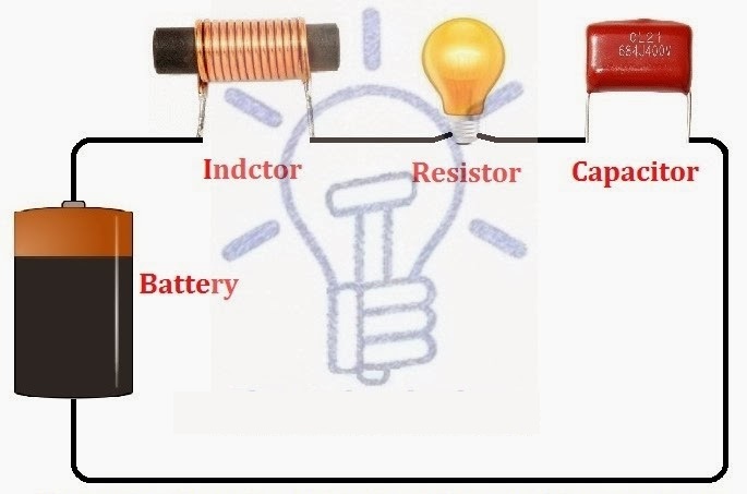
A circuit, often known as an electrical circuit, is a closed-loop channel that provides a current return path. This is a narrow conducting channel through which current can flow.
Types of Electric Circuits
There are many types of electric circuits including:
- Series Circuit
- Parallel Circuit
- Series-Parallel Circuit
- Star-Delta Circuit
- Resistive Circuit
- Inductive Circuit
- Capacitive Circuit
- Resistive, Inductive (RL Circuit)
- Resistive, Capacitive (RC Circuit)
- Capacitive, Inductive (LC Circuits)
- Resistive, Inductive, Capacitive (RLC Circuit)
- Linear Circuit
- Non-Linear Circuit
- Unilateral Circuits
- Bi-lateral Circuits
- Active Circuit
- Passive Circuit
- Open Circuit
- Short Circuit
- Closed Circuit
We’ll go through each of them briefly below.
Series Circuit
All of the electrical parts (voltage or current sources, inductors, capacitors, resistors, and so on) are connected in series in this circuit, which means there is only one path for electricity to go and no additional branches. A series circuit is made up of multiple resistances that are connected one after the other. An end-to-end or cascade connection is another name for this type of connection. The flow of current follows a single path.
Properties of Series Circuit
Every resistance is crossed by the same current. The total of the various voltage falls across the resistances is the supply voltage V.
V = {V}_{1} + {V}_{2} + {V}_{3} + …..+ {V}_{n}
The total of the various resistances is equal to the comparable electrical resistance. Individual resistances are overwhelmed by the equivalent resistance (R > R1, R > R2, …., R > Rn).
Parallel Circuit
All of the electrical elements in this circuit (voltage or current sources, inductors, capacitors, resistors, and so on) are linked in parallel, i.e. there are numerous channels for electricity to travel down, and the circuit’s minimum branches are two. A parallel circuit is one in which many resistances are connected across one another in such a way that one terminal of each resistance is connected to form a junction point, and the remaining end is also connected to make another point.
Properties of Parallel Circuits
A similar potential difference is shared by all resistances at the same time. The total current is divided into the number of parallel routes equal to the number of resistances. The sum of all the individual currents is always the aggregate current.
I = {I}_{1} + {I}_{2} + {I}_{3} + …..+ {I}_{n}
The reciprocal of a parallel circuit’s equivalent resistance is equal to the total of the reciprocals of the individual resistances. The smallest of all resistances is the equivalent resistance (R < R1, R < R2, R < Rn).
The equivalent conductance is the result of adding the single conductances mathematically. The equivalent resistance is smaller than the smallest of all parallel resistances.
Series-Parallel Circuit
A series-parallel circuit is one in which certain circuit elements are connected in series while others are connected in parallel. To put it another way, this is a circuit that combines series and parallel circuits.
Star-Delta Circuit
This is not a parallel, series, or series-parallel circuit. Electrical elements are connected in this circuit in such a way that the configuration is undefined in terms of Series, Parallel, or Series Parallel. The Star-Delta Transform or Delta-Star transformation can be used to solve these types of circuits.
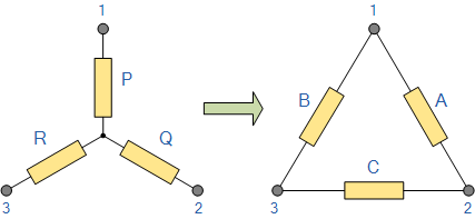
More derived circuits of the Series, Parallel, and Series-parallel circuits are listed below:
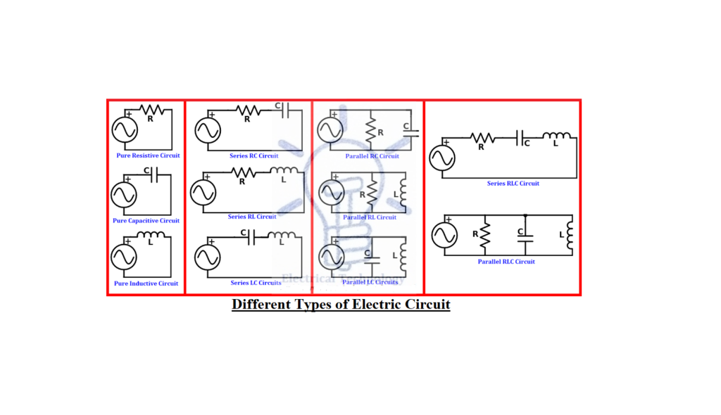
- Pure Resistive Circuit
- Pure Inductive Circuit
- Pure Capacitive Circuit
- Resistive, Inductive Circuit i.e. RL Circuit
- Resistive, Capacitive Circuit i.e. RC Circuit
- Capacitive, Inductive Circuits i.e. LC Circuits
- Resistive, Inductive, Capacitive Circuit RLC Circuit
All of the above-mentioned components or elements can be connected in series, parallel, or series-parallel configurations in the circuits above. Visit here to see all of the different types of electric circuits completely.
Let’s look at some more electric circuits that you should be familiar with before beginning to study an electric circuit or network.
Linear & Non-Linear Circuits
Linear Circuit
A linear circuit is an electric circuit with constant circuit parameters such as resistance, inductance, capacitance, waveform, and frequency. In other terms, a linear circuit is one whose parameters do not change with regard to current and voltage.
Non-Linear Circuit
A non-linear circuit is one in which the parameters vary in relation to current and voltage. In other terms, a nonlinear circuit is one in which the circuit parameters (resistance, inductance, capacitance, waveform, frequency, and so on) are not constant.
Unilateral & Bi-lateral Circuits
Unilateral Circuits
In unilateral circuits, the function of the circuit changes as the supply voltage or current changes direction. To put it another way, a unilateral circuit only permits the current to pass in one direction. Because it does not perform rectification in both supply directions, the diode rectifier is the best example of a unilateral circuit.
Bi-Lateral Circuits
The property of a circuit in a bi-lateral form does not change as the supply voltage or current changes direction. Bi-lateral circuits, in other terms, allow current to flow in both directions. The best description of a bi-lateral circuit is a transmission line because the circuit parameters stay constant regardless of which direction the supply comes from.
Circuit’s Parameters, Constants and Related Terms
Circuit parameters or constants refer to the various components or elements used in electric circuits, such as resistance, capacitance, inductance, frequency, etc. These variables can be grouped or dispersed. These parameters can determine the specification of each circuit which are summarized below:
Active Circuit
An active circuit is a circuit that contains one or more EMF (Electro Motive Force) sources.
Passive Circuit
The term “passive circuit” refers to a circuit that has no EMF sources.
Open Circuit
An open circuit is one in which there is no return channel for current to flow (i.e. one that is not completed). In other terms, an open circuit is one in which the voltage tends to 0zero and the current approaches to infinity.
An open circuit occurs when a circuit contains a damaged electrical wire or electronic component or when the switch is turned off. The bulb is not lighting in the diagram below because either the switch is turned off or the electrical line is faulty.
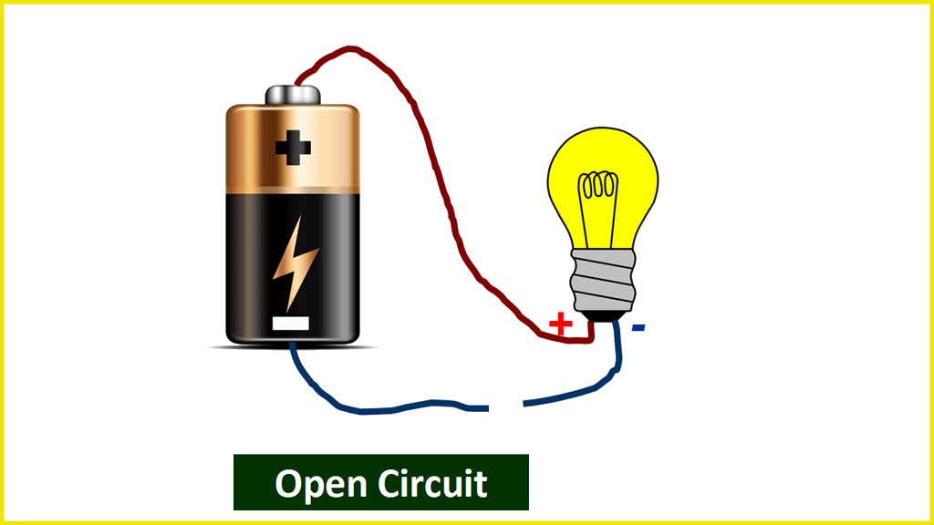
A circuit with an open switch and a light bulb attached to the battery is an example of an open circuit. As a result of the open circuit, the bulb will not light.
Short Circuit
A short circuit is a circuit that has a return channel for current to flow in it (i.e. completed circuit). A short circuit is a circuit in which the voltage tends to infinity and the current tends to zero.
A short circuit occurs when both points (+ and –) of a voltage source in a circuit become connected for any reason. In this case, the maximum current begins to flow. Short circuits occur when conducting electrical lines become joined or even due to shorting in the load.
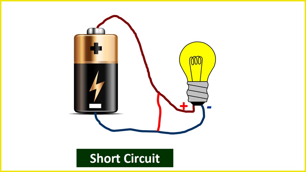
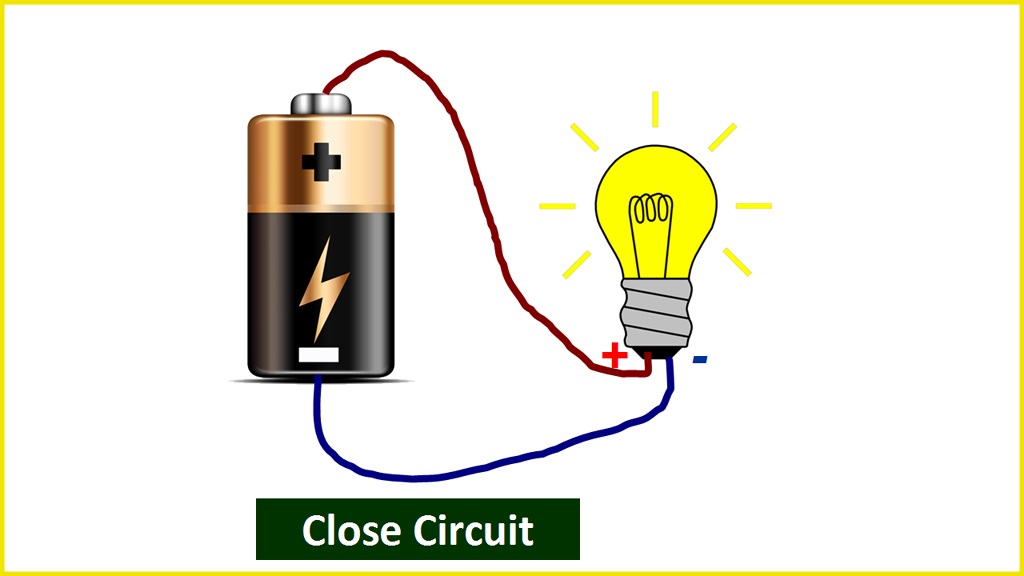
A circuit with a close switch and a light bulb attached to the battery is an example of a short circuit. As a result of the completed circuit, the light illuminates.
Closed Circuit
Closed Circuit is the term used when a load in a circuit functions on its own. The value of the current flow, in this case, is determined by the load.
Parts of Electric Circuits and Networks & Other Related Terms
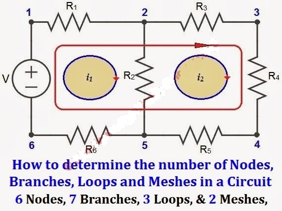
Node
A node refers to the point or junction where two or more circuit elements (resistor, capacitor, inductor, etc.) connect.
Branch
Branch refers to the segment or section of a circuit that occurs between two junctions. One or more parts can be joined in a branch, which has two endpoints.
Loop
A loop is a closed channel in a circuit that can contain more than two meshes, i.e. a loop can contain multiple meshes, but a mesh can only include one loop.
Mesh
Mesh is a closed loop that does not contain any other loops or paths that do not contain any other pathways.
Buy Equipment or Ask for a Service
By using Linquip RFQ Service, you can expect to receive quotations from various suppliers across multiple industries and regions.
Click Here to Request a Quotation From Suppliers and Service Providers
Read More on Linquip
- The 8 Best Circuit Breaker Locators
- What Are Resistors for LED Circuits? (Clear Guide)
- What is Resistive Circuit? Example & Diagram
- What is Linear Circuit? Example & Diagram
- What is Capacitive Circuit? Formula & Function
- What is LC Circuit? Formula, Equitation & Diagram
- What is RL Circuit? Formula, Equitation & Diagram
- What is RC Circuit? Formula, Equitation & Diagram
- What is Parallel Circuit? Definition & Example
- What is Series Circuit? Definition & Example
- What is Closed Circuit? Definition & Example
- What is Short Circuit? A Clear Definition & Protection Guide
- What is Open Circuit? Diagram & Example
- What is Inductive Circuit?
- Difference Between Linear and Nonlinear Circuits
- Types of Electric Circuits: All Classification with Application
- What are the Differences Between Series and Parallel Circuits?
- What is AC Circuit and Its Characterization?
- Circuit Breaker vs Fuse- What are the Main Differences?
- How does a Circuit Breaker Work?
- What is the Equivalent Circuit of Transformer?
- Potentiometer Connection, Working, Circuit Diagram, & Wiring Guide
- Difference between Series and Parallel Circuits | What are they Completely?
- Difference Between Relay and Circuit Breaker: Everything You Need to Know
- Difference Between Isolator and Circuit Breaker: Ultimate Guide
- Piezoelectric Transducer and Its Impressive Applications in Electric Circuits
- What is Vacuum Circuit Breakers?
- Types of Circuit Breaker: A Basic Guide to Know Different Classifications



Short circuit explanation is incorrect in that the short across the lamp load reduces the potential across the lamp to where the lamp won’t light.
Thank you for your consideration. Please check our other posts.