What is LC Circuit? Due to frequency properties such as frequency Vs current, voltage, and impedance, circuits with L and C elements have unique characteristics. At some frequencies, these features may have an abrupt minimum or maximum. These circuits are mostly used in transmitters, radio receivers, and television receivers. Consider an LC circuit that has both a capacitor and an inductor linked in series across a voltage supply. This circuit’s connection has the unusual attribute of resonating at a specific frequency, known as the resonant frequency. This post explains what an LC circuit is and how a simple series and parallels LC circuit works.
What is LC Circuit?
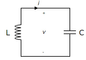
An LC circuit, also known as a tank circuit, a tuned circuit, or a resonant circuit, is an electric circuit that consists of a capacitor marked by the letter “C” and an inductor signified by the letter “L.” These circuits are used to generate signals at a specific frequency or to accept a signal from a more complex signal at a specific frequency. LC circuits are basic electronics components found in a wide range of electronic devices, particularly radio equipment, where they are employed in circuits such as tuners, filters, frequency mixers, and oscillators. The basic purpose of an LC circuit is to oscillate with the least amount of damping possible.

An LC circuit is an electric circuit that consists of an inductor (represented by the letter L) and a capacitor (represented by the letter C). Both are connected in a single circuit in this case. A tank circuit, resonant circuit, or tuned circuit are all terms used to describe an LC circuit. LC circuits are used in a variety of electronic devices, such as radio equipment, and circuits such as filters, oscillators, and tuners.
In many situations, the LC circuit is a useful basis to employ because we can assume that there is no energy loss even if there is resistance. However, any implementation will result in loss due to the minor electrical resistance in the connecting wires or components if we are to be practical. This circuit is utilized because it can oscillate with the least amount of dampening, resulting in the lowest possible resistance. Despite this, the majority of the circuits operate with some loss.
An LC circuit can conserve electrical energy when it oscillates at its natural resonant frequency. The capacitor will store energy in the electric field (E) between its plates based on the voltage it receives, but an inductor will accumulate energy in its magnetic field depending on the current (B).
Definition and Principle of LC Circuit
A basic example of an inductor-capacitor network is the di-elemental LC circuit discussed in the preceding paragraphs. It’s also known as a second-order LC circuit to distinguish it from more complex LC networks with more capacitors and inductors. Multiple resonant frequencies can be found in LC networks with more than two reactances.
A system’s undamped or natural frequency is referred to as a resonant frequency. The resonant frequency of LC circuits is usually defined by the impedance L and capacitance C. The network order, on the other hand, is a rational function order that describes the network in complex frequency variables. In most cases, the order equals the number of L and C elements in the circuit and cannot be exceeded.
Series LC Circuit Resonance
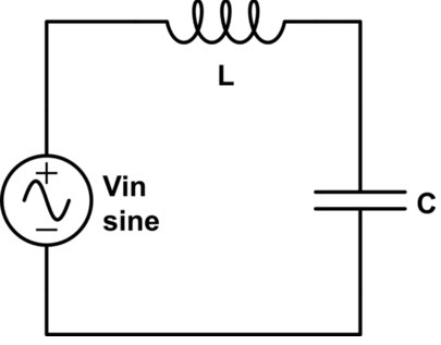
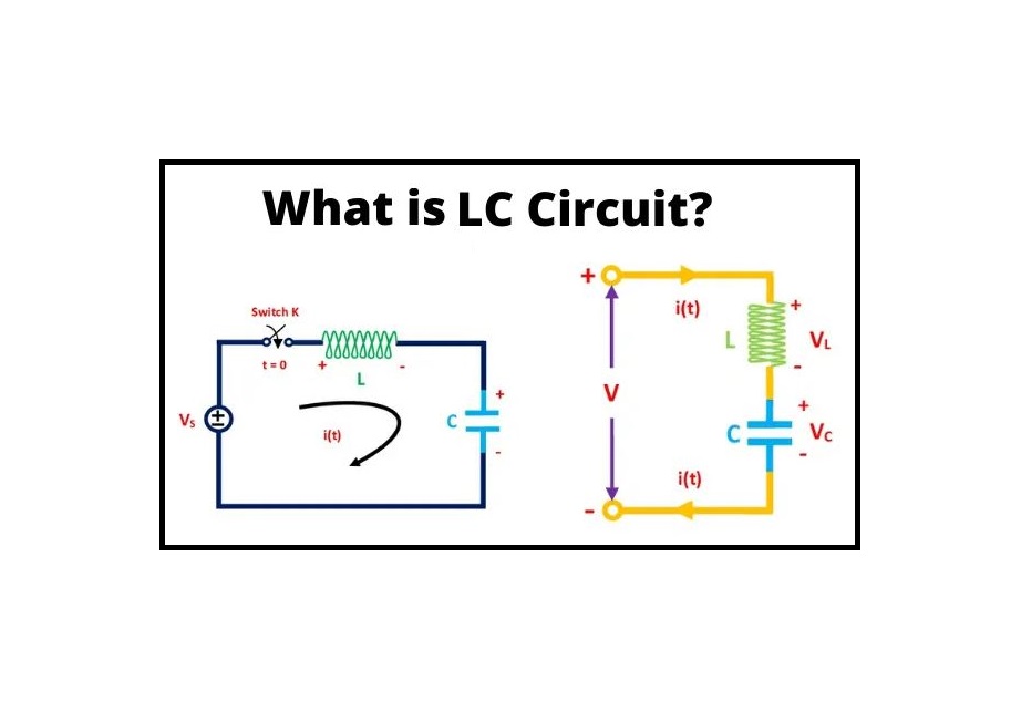
The capacitor ‘C’ and inductor ‘L’ are both connected in series in the series LC circuit design, as shown in the circuit below. The total voltage across the open terminals is simply the sum of the voltage across the capacitor and inductor. The current flowing through the +Ve terminal of the LC circuit equals the current flowing through the inductor (L) and the capacitor (C) (V = VL + VC, i = iL = iC).
When the amplitude of the ‘XL‘ inductive reactance grows, the frequency also increases. Similarly, as the amplitude of the ‘XC‘ capacitive reactance reduces, the frequency lowers.

The two reactances XL and XC have the same magnitude but the opposite sign at a certain frequency. As a result, this frequency is referred to as the resonant frequency, and it is denoted as in the LC circuit.
Therefore, at resonance
{X}_{L} = {-X}_{C}
{\omega }_{L}=\frac{1}{{\omega}_{C}}, \omega ={\omega }_{0}=\frac{1}{\sqrt{LC}}
Which of the following is the circuit’s resonant angular frequency? The following formula is used to convert angular frequency to frequency.
{f}_{0}=\frac{{\omega }_{0}}{2\pi \sqrt{LC}}
The two resonances XC and XL cancel each other out in a series resonance LC circuit design. The resistance of the coil’s windings often opposes the flow of electricity in actual, rather than ideal, components. As a result, at resonance, the current provided to the circuit is at its maximum.
When the f/f0 ratio is the highest and the circuit’s impedance is the lowest, the circuit is said to be an acceptance circuit.
For f<f0, XL << (-XC), the circuit is capacitive, and for f<f0, XL>> (-XC), the circuit is inductive.
Parallel LC Circuit Resonance
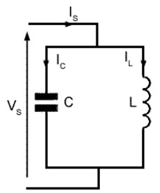
The capacitor ‘C’ and inductor ‘L’ are both connected in parallel in the parallel LC circuit configuration, as shown in the circuit below. The total voltage across the open terminals is simply the sum of the voltage across the capacitor and inductor. The current flowing through the +Ve terminal of the LC circuit equals the current flowing through the inductor (L) and the capacitor (C) (V = VL = VC, i = iL + iC).
Assume the coil’s internal resistance “R.” The reactive branch currents are the same and opposite when two resonances, XC and XL, are present. As a result, they cancel each other out, leaving the key line with the smallest amount of current. In this state, the total current is at its lowest, while the total impedance is at its highest. The resonance frequency is calculated as f0 = ω0/ 2π.
It’s worth noting that the current of any reactive branch isn’t zero at resonance; instead, each one is calculated separately by dividing source voltage “V” by reactance “Z”.

As a result of Ohm’s equation I=V/Z, a rejector circuit can be classified as inductive when the line current is minimum and total impedance is maximum at f0, capacitive when above f0, and inductive when below f0. Visit here to see some differences between parallel and series LC circuits.
Applications of LC Circuit
The resonance of series and parallel LC circuits is most commonly used in communications systems and signal processing.
Tuning radio TXs and RXs is a popular use for an LC circuit. When we tune a radio to a specific station, for example, the circuit will be set to resonance for that particular carrier frequency.
Voltage magnification is achieved using a series resonant LC circuit.
A parallel resonant LC circuit is used to provide current magnification and is also utilized as the load impedance in RF amplifier circuits, with the amplifier’s gain being maximum at the resonant frequency.
Induction heating uses both series and parallel resonant LC circuits.
These circuits function as electronic resonators, which are used in applications such as amplifiers, oscillators, tuners, filters, graphic tablets, mixers, contactless cards, and security tags XL and XC.
Thus, the LC circuit, the operation of series and parallel resonance circuits, and their applications are all covered. We hope you’ve gained a better understanding of this idea as a result of this discussion. In addition, if you have any questions or suggestions about this concept or electrical and electronics projects, please leave them in the comments area below. Here is a question for you, what is the difference between series resonance and parallel resonance LC Circuits? Share your comments below.
Buy Equipment or Ask for a Service
By using Linquip RFQ Service, you can expect to receive quotations from various suppliers across multiple industries and regions.
Click Here to Request a Quotation From Suppliers and Service Providers
Read More In Linquip
- Types of Electric Circuits: All Classification with Application
- How does a Circuit Breaker Work?
- What is Resistive Circuit
- What is Linear Circuit
- What is RL Circuit
- What is RC Circuit?
- What is RLC Circuit
- What is Capacitive Circuit?
- Types of Resistor: Classification, Application, and Finally Clarification
- What is Parallel Circuit? Definition & Example
- What is Series Circuit? Definition & Example
- What is Closed Circuit? Definition & Example
- What is Short Circuit? A Clear Definition & Protection Guide
- What is Open Circuit? Diagram & Example
- Difference Between Linear and Nonlinear Circuits
- Types of Electric Circuits: All Classification with Application
- What are the Differences Between Series and Parallel Circuits?


