Types of DC Generators – DC generators are electrical devices for converting mechanical energy to electrical power. Cutting magnetic flux by the armature produces EMF based on Faraday’s Laws and electro-induction. EMF is the cause of current flow in the circuit.
MMF is required by a DC generator to establish flux in its magnetic circuit. Field excitation is used to get the MMF required to establish flux in a dc generator’s magnetic circuit. When a DC voltage is provided to a DC generator’s field windings, current flows through the windings, creating a stable magnetic field. Field excitation is the term for this. DC generators are available from a wide range of Suppliers and Companies, as well as manufacturers and distributors, and Linquip has a large selection of DC Generators for Sale.
Linquip’s website comprehensively lists DC generator services for all OEM fleets. Vendors from Linquip can help you with this. To learn more about how to connect with a varied collection of service providers who consistently produce high-quality products, please contact DC Generators Experts.
Types of DC Generators
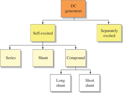
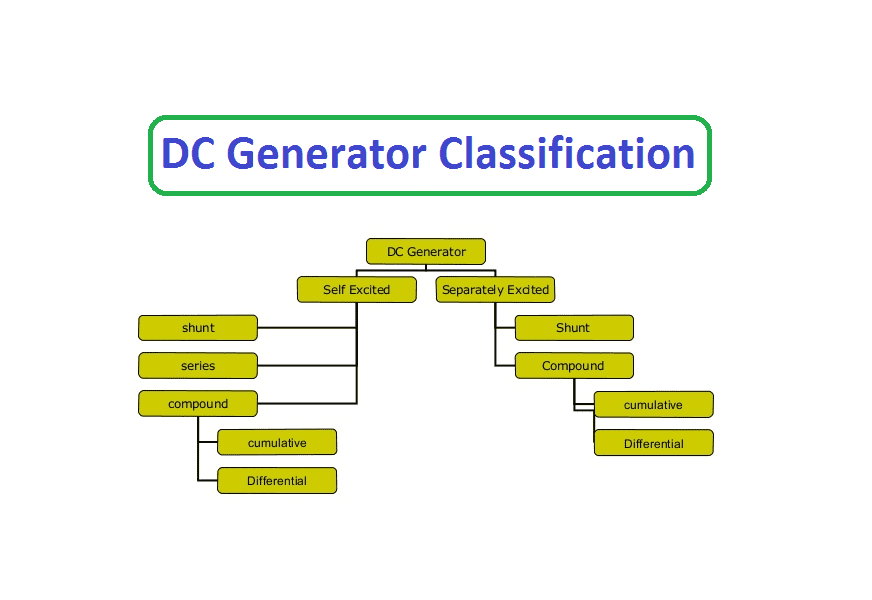
DC generators are categorized into three main types based on the methods of field excitation: Permanent Magnet, Separately Excited, and Self-Excited DC generators. The first type excites the field coils by using Permanent magnets, while the separately excited one includes an external force for excitation. A self-excited DC generator includes another generator itself and field coils excited by it. The diagram for DC generator types is as below, and the permanent magnet field is not included because of not widely used in the industry.
Permanent Magnet DC Generators
This kind of generator utilizing permanent magnets for creating the flux in the magnetic circuit is known as the Permanent magnet DC generator and is the most basic type of generator. There are an armature and one or many permanent magnets placed around the armature. This type cannot supply much power due to the design of the generator and does not employ it in industry applications. Permanent magnet DC generators usually are used in small applications, the same as dynamos in motorcycles.
Figure 2 illustrates the basic form of the permanent magnet DC generators, and as we know, voltage is created when the wire cuts the field and the amount of it is dependent on the wire loops and the rate of rotation in the field. Also, the amount of the voltage is the function of the angle between the magnetic flux and the moving surface. As each loop rotates, the voltage varies from 0 to the maximum amount of itself as the function of the angle and makes an absolute amount of sinusoidal voltage. Increasing the number of loops at different angles makes the voltage to be constant at its maximum value.

the induced voltage is calculated as:
V_{ind}=Blv
where:
Vind = induced voltage, in V
B = flux density that is perpendicular to the motion, in Web/m2
l = length of the conductor, in m
v = velocity of the conductor, in m/s
Separately Excited DC Generators
An external DC source (e.g., battery) is used in this system for energizing field magnets. As the rotation speed increases, it can provide a higher EMF and voltage in the output. The circuit diagram for the separately excited DC generators is illustrated in Figure 3, and the symbols are as below:
- IL = Load current
- Ia = Armature current
- Eg = Generated EMF (Electromagnetic Force)
- V = Terminal voltage
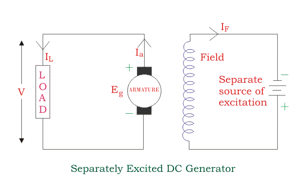
The generated power and the delivered power to the external force can be calculated as:
I_a=I_l=I
V=IR_{a}
P_g=E_g\times I
P_l=V I
Self-Excited DC Generators
Self-excited DC generators have field magnets that are energized by their own supplied current, and the field coils are connected to the armature internally. There is always some flux in the poles because of the residual magnetism. As the armature rotates, some current is produced, and this small current flows through the field coils with the load, strengthening the pole flux. By increasing the pole flux, the EMF and the current increase, and the accumulative process is continuing until the excitation is necessary. Self-excited DC generators are classified based on the field coils and their position as follows:
- Shunt Wound Generators
- Compound Wound Generators
- Series Wound Generators
Shunt Wound DC Generators
The field windings are connected to the armature conductors parallelly to excite the generator. Field windings are the insulated current-carrying coils that produce the needed magnetic field for the excitation of the generator. A shunt generator excites by residual magnetism in poles, and the field windings have the same voltage as the terminals in the shunt-wound generator, while the actual value of this voltage depends on the load and its speed. The circuit diagram for this type is as below:
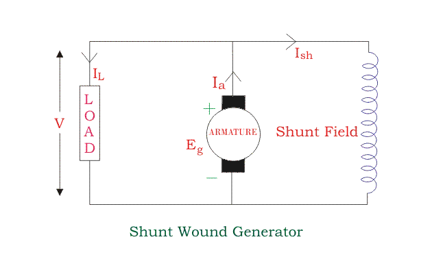
where:
- V = Terminal voltage
- Eg = Generated EMF
- Ish = Current flowing through the shunt field
- Ia = Armature current
- IL = Load current
- Rsh = Shunt winding resistance
- Ra = Armature resistance
Armature current Ia consists of two parts of shunt field current Ish and load current IL.
I_a=I_{sh}+I_l
When the IL is the maximum, the effective power for the load would be the maximum. As a result, it is better to keep the shunt current as low as possible. So it is reasonable to keep the resistance of the shunt high.
I_{sh}=\frac{V}{R_{sh}}
V=E_g-I_aR_a
Generated power and power delivered to the load are:
P_g=E_g\times I_g
P_l=V\times I_l
Series wound generators
The field winding is in series with armature conductors in series-wound generators. Figure 5 is the circuit diagram for this generator. The current in the field coil is the same as the load and flows in both. Field windings are designed with few turns and use thick wires to have low electrical resistance. The circuit diagram for this type is as below:
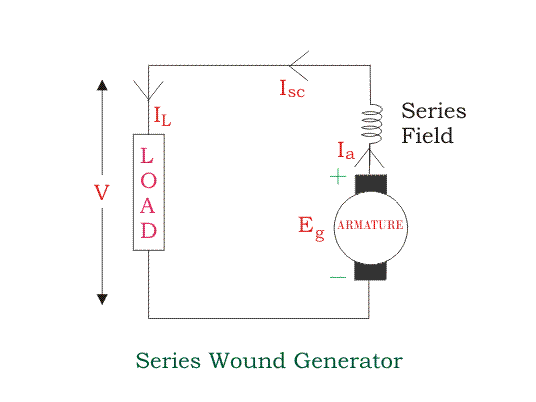
I_a=I_l=I_{sc}=I
V=E_g-I^{2}\times R_a
Generated power and power delivered to the load are:
P_g=I\timesE_g
P_l=I\timesV
Compound Wound DC Generators
The output voltage and EMF depend on the load current in the series wound type, and on the other hand, in the shunt type, the output is proportional to the inverse of the load current. To overcome the disadvantage of both types, compound wound generators are available, combining both series and shunt. The circuit of the compound wound generators includes both series and shunt field wounding. There are a series and a parallel winding with the armature and include two types of short shunt compound wound generator and long shunt compound wound generator.
Long Shunt Compound DC Generators
In long shunt compound DC generators, the shunt windings are parallel with both series field and armature. The circuit diagram for this type is as below:
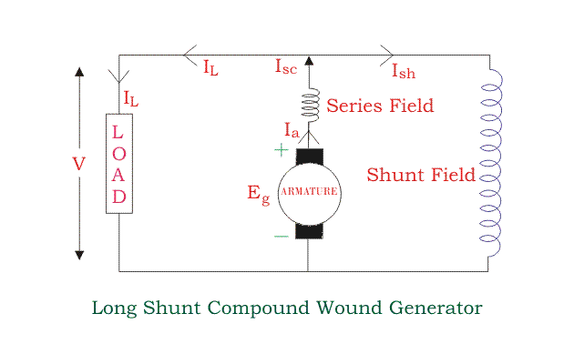
The currents in the circuit are:
I_{sh}=\frac{V}{R_{sh}}
I_{cs}=I_l+I{sh}
I_{cs}=I_a
The load voltage is equal to:
V=E_g-I_a(R_a-R{sc})
Generated power and the delivered power to the load are:
P_g=I_G\times E_g
P_l=I_G\times V
Short Shunt-Wound DC Generator
In short type, an armature is parallel with the shunt field windings, as shown in the following figure:
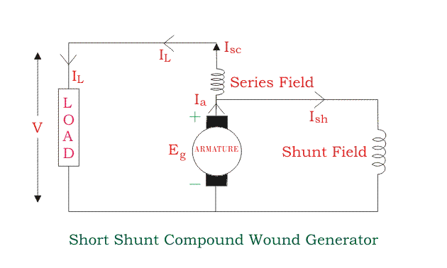
The currents in this system are:
I_{sc}=I_{l}
I_{sh}=\frac{V+I_{sc}R_{sc}}{R_{sh}}
I_{a}= I_{sc}+I_{l}
The load voltage, load power, and generated power are:
V=E_g-I_aR_a-I_{sc}R{sc})
P_l=I_G\times V
P_g=I_G\times E_g
Download Classification of DC Generators PDF
Buy Equipment or Ask for a Service
By using Linquip RFQ Service, you can expect to receive quotations from various suppliers across multiple industries and regions.
Click Here to Request a Quotation From Suppliers and Service Providers
Read More on Linquip
- Power System Services
- Power System Maintenance Services
- Power System Installation Services
- Power Systems Services in Texas
- Power System Maintenance Services in Texas
- Power System Installation Services in Texas
- What are the parts of AC Generators?
- A Clear Classification of AC Generators
- Types of Generators: Learn the Basics, Get the Most Outfit!
- Types of Synchronous Motors: A Full Description
- Types of Induction Motor: A Concise and Useful Guild
- All About DC Motor Types and Their Applications
- Working Principle of Diesel Generator + Diagram
- Working Principle of AC Generator
- The 10 Best Solar Generator
- The Best Diesel Generator of 2022
- The 5 Best Gasoline Generators of 2022
- The 8 Best Standby Generator of 2022
- Best Dual Fuel Generator of 2022
- What is an Induction Generator? An Ultimate Guide
- Best Portable Generators: Everything You Need to Know
- What are The Electric Generator Parts?
- Parts of Generator: a Simple, Yet Useful Guide
- Single-phase generators; 5 essential steps to know single-phase generators
- DC Generator Repair, Maintenance & Testing (Clear Guide)



Why in a shunt wound generator output is proportional to inverse of load current?
I need losses in DC generator
Very nice and beautiful chapter