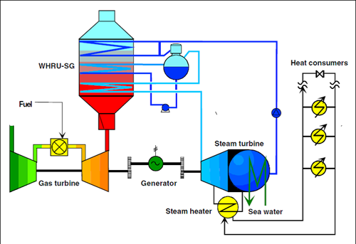
The combined cycle gas turbine is widely used to generate electricity from natural gas. The gas is burned in a high-temperature gas turbine coupled to a generator. Exhaust gases from the turbine are utilized to generate steam that is then fed to a conventional steam turbine and another generator.
Basics of Combined Cycle Gas Turbine
A combined cycle power plant consists of heat engines that work together from the same heat source, converting that heat into mechanical power. Combining cycle gas turbine (CCGT) plants are the most common type for producing electricity on land. Marine propulsion also uses the same concept, which is known as the combined gas and steam (COGAS) plant. When two or more thermodynamic cycles are combined, overall efficiency is improved, resulting in lower fuel costs.
Increasing the efficiency of a system by 50–60% can be accomplished by combining multiple streams of work. A combined cycle, for example, may have an overall efficiency as high as 64% compared with a simple cycle’s efficiency of 34%. That’s more than 84% of a Carnot cycle’s theoretical efficiency. A heat engine can only utilize part of the energy contained in its fuel (usually less than 50%). As a result, the leftover heat (in hot exhaust gases) from combustion is wasted.
We are talking here about a combined cycle gas turbine (CCGT). Combined cycles are widely used in stationary and marine power plants and include large gas turbines (which operate by the Brayton cycle). A steam power plant (which is based on the Rankine cycle) is powered by hot exhaust from the turbine. In base-load operation, these units provide thermal efficiency of around 64%. Steam power plants, on the other hand, can reach efficiency levels of 35 to 42% when they run on a single cycle.
CCGTs are being used in a growing number of new power plants. Natural gas or coal-derived synthesis gas is used in stationary CCGTs. Ships run on fuel oil.
Even though multiple-stage turbines and steam cycles are also feasible, CCGT plants offer advantages for both electricity production and marine power. The gas turbine cycle can often be started instantly, so power is available immediately. This eliminates the need for expensive peaker plants or allows a ship to maneuver freely. Eventually, the secondary steam cycle will warm up over time, increasing fuel efficiency and generating more power.
Working Principle of Combined Cycle Gas Turbine
Here, it is described how a combined-cycle plant works with waste heat from a gas turbine to increase efficiency and electrical output.
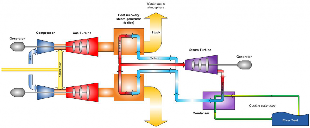
- Gas turbine burns fuel
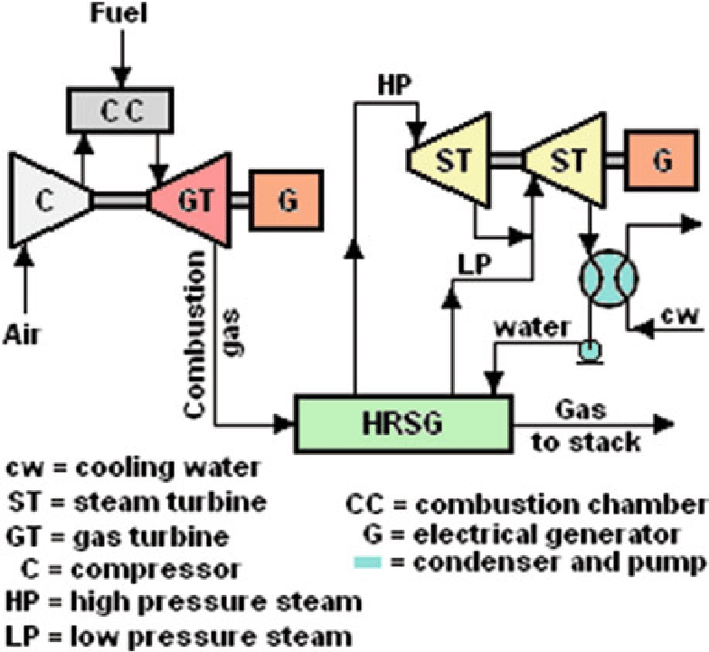
By compressing air, the gas turbine mixes it with fuel that has been heated to an extremely high temperature. Gas turbine blades spin as the hot air-fuel mixture passes through them. As the turbine spins, a generator generates electricity using some of the spinning energy.
2. Heat recovery system captures exhaust
Gas turbine exhaust heat escapes through the exhaust stack unless it is captured by a heat recovery steam generator (HRSG). By using the exhaust heat of the gas turbine, the HRSG produces steam that powers the steam turbine.
3. Steam turbine delivers additional electricity
Steam turbine energy is sent to the generator drive shaft and converted into additional electricity.
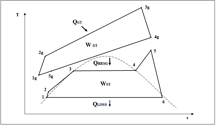
Two power plant cycles make up the thermodynamic cycle of the combined cycle. One of them is the Joule or Brayton cycle, a gas turbine cycle, and the other is the Rankine cycle, a steam turbine cycle. A gas turbine power plant cycle is 1g-2g-3g-4g-5g-1g, the topping cycle. Heat is transferred, and work is done in high-temperature regions.
The bottoming cycle consists of the Rankine steam cycle 1-2-3-4-5-6-1, taking place at a low temperature. As part of the bottoming cycle, the waste heat is recovered from high-temperature exhaust gases and transferred into water and steam. Gas turbine exhaust gases reject heat during the constant pressure process 4g-1g. In the processes 1-2, 2-3, and 3-4, feed water, wet steam, and superheated steam absorb some of this energy.
Technical Considerations
For both the Rankine cycle and the Brayton cycle, it is important to consider some principles when designing different components of the combined cycle gas turbine.
Material
A heat engine’s efficiency, which represents the fraction of its input energy that can be converted into useful work, is limited by the temperature difference between the heat entering it and the exhaust heat leaving it.
Water is the working medium in a steam power station. Components need to be strong and bulky in order to handle high-pressure steam. Rather than using inexpensive steel, high temperatures require expensive alloys based on nickel or cobalt. Practical steam temperatures are limited to 655 degrees Celsius by these alloys, while the lower temperature of a steam plant is determined by the temperature of the cooling water. The maximum efficiency of a steam plant is 35–42% with these limits.
The open-circuit gas turbine cycle consists of a compressor, combustor, and turbine. In gas turbines, lower quantities of expensive materials may be needed to withstand the high temperatures and pressures. The firing temperature (the input temperature to the turbine) in this type of cycle is relatively high (900 to 1,400 °C). The output flue gas temperature is also high (450-650°C). As such, it is high enough to provide heat to a second cycle that uses steam as the working fluid (the Rankine cycle).
An HRSG with a live steam temperature of 420 to 580 °C uses the exhaust heat from the gas turbine to generate steam for a combined cycle power plant. Most Rankine cycles utilize water from lakes, rivers, seas, or cooling towers in order to cool the condenser. These temperatures can drop as low as 15 °C.
Size
The costs of plants are influenced by plant size. As plants grow larger, economies of scale (lower initial costs per kilowatt) and efficiency improve. A typical large-scale power plant would contain a primary gas turbine of 270 MW coupled with a steam turbine of 130 MW, yielding a combined output of 400 MW. Depending on the size of the power station, these sets might number between 1 and 6.
The combined cycle unit is composed of one or more of these gas turbines, each equipped with a waste heat steam generator that provides steam to one or more steam turbines, forming a combined cycle unit or block. There is a wide range of combined cycle block sizes, from 50 MW up to well over 1300 MW.
Fuel
Natural gas is usually used as a fuel in combined cycle plants, but other fuels such as fuel oil and synthesis gas can also be used. Supplementary fuel options include coal, fuel oil, and natural gas. There is also the option of using biofuels. A solar combined cycle power station combines solar power with another fuel to reduce fuel costs and for environmental reasons. Nuclear power plants of the next generation can use a Brayton topping cycle that offers a higher temperature range as well as a Rankine bottoming cycle that increases thermal efficiency.
Small-scale combined cycle plants using renewable fuels can be used to meet electricity needs in remote areas where an extension of a gas pipeline would be impractical or cannot be economically justified. Gasification and burning of agricultural and forestry waste are used instead of natural gas, which is readily available in rural areas.
Supplementary Firing
Fuel can be added to the HRSG after the gas turbine for supplementary combustion. Duct burners are referred to as supplementary burners as well. Because turbine exhaust gases (flue gas) contain oxygen, duct burning is possible. A temperature limit at the inlet of the gas turbine forces the fuel to be burned at a higher rate than its stoichiometric ratio. A portion of the compressed air flow bypasses the burner in gas turbine designs for the purpose of cooling the turbine blades. Due to the hot exhaust gas from the turbine, there is no requirement for a regenerative air preheater as in the case with conventional steam plants.
Combined cycle power plants are more efficient without supplementary firing. A more flexible plant operation, however, makes a marine CCGT safer by allowing ships to operate as-is even when equipment fails. It is also more profitable to run a flexible stationary plant.
Due to the higher temperatures in the flue resulting from duct burning, the quantity of steam is increased (e.g. to 84 bar, 525 degrees Celsius). Thus, steam cycle efficiency is improved. Due to the very high efficiency of duct burners with partial loads, supplemental firing allows the plant to respond to fluctuations in electrical load. The higher steam production can compensate for a breakdown of another unit. As a supplementary fuel, coal can also be burned in the steam generator.
The temperature of the exhaust can be raised up to 800 °C or even 1000 °C when supplementary firing takes place. In most cases, supplementary firing does not increase efficiency. When fired to 700-750 °C, it can raise the efficiency of single boilers; when fired to numerous boilers, however, the flexibility should be the most attractive element.
Natural gas and light oil are the main fuels for gas turbines. Fuel treatment equipment is required for crude oil, residuals, and some distillates, which contain corrosive components. Additionally, ash deposits from these fuels can lead to gas turbine deratings of up to 15%. However, they may still serve as economically attractive fuels in combined-cycles plants.
Configuration
Multi- and single-shaft combined-cycle systems are both possible. Steam systems can also be configured in a variety of ways. In order to generate electricity with the greatest fuel efficiency, HRSGs with modular pre-engineered components are employed. As well as being the lowest in initial costs, these unfired steam cycles often consist of a single-shaft system that is installed as a unit.
In general, supplementary-fired multi-shaft combined-cycle systems are selected depending on the fuel, application, or situation. For example, a cogeneration combined-cycle system might need more heat or higher temperatures, and electricity takes second place.
Multiple shaft systems with supplementary firing can provide a greater range of operating temperatures or heat to electric power. If low-quality fuels such as brown coal or peat are burned, closed-cycle helium turbines may be used as the topping cycle to avoid the need for even more gasification and fuel processing that would be required by a conventional gas turbine.
Single-Shaft Configuration
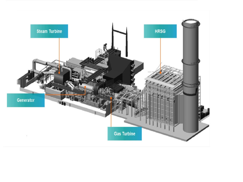
The typical single-shaft system consists of a gas turbine, a steam turbine, a generator, and a heat recovery steam generator. Both the steam turbine and gas turbine are linked on the same shaft to a single electrical generator. The operation of this arrangement is simpler, smaller, and requires less startup money.
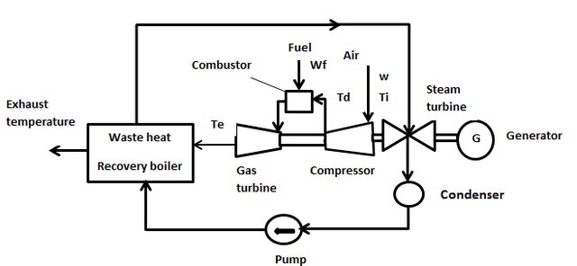
The flexibility and reliability of a single-shaft arrangement can be less than a multi-shaft system. Operators can add operational flexibility with some expense: Most often, a gas turbine is operated as a peaking plant. In these plants, the shaft of the steam turbine can be disconnected by a synchro-self-shifting (SSS) clutch, which can be used either for start-up or simple cycle operation of the gas turbine.
To improve reliability, another less common option is to increase the steam turbine’s heat output or to run it independently: for example, with fresh air blown through the duct and a clutch on the gas turbine side.
Multi-Shaft Configuration
Up to three gas turbines are usually connected to one steam system for a multi-shaft system. The operation and maintenance costs can be reduced by having just one large steam turbine and heat sink. A larger steam turbine can also run at higher pressures, thereby achieving a more efficient steam cycle. The initial cost of a multi-shaft system is approximately 5% higher.
The size of the plant and the number of gas turbines required may also determine which type is the most cost-effective. Having more pieces of equipment can make operating and maintaining a collection of single-shaft combined cycle power plants more expensive. The business can, however, save interest costs by adding plant capacity as needed.
Efficiency
It is possible to achieve high input temperatures and low output temperatures by combining the gas and steam cycles. Because the cycles use the same fuel source, their efficiency is increased. A combined-cycle plant operates between the high temperature of the gas turbine and the waste heat temperature from the steam cycle condensers in order to set up its thermodynamic cycle. Due to this large temperature range, the cycle has a high Carnot efficiency. Although the actual efficiency is lower than that of the Carnot plant, it is still higher than that of either plant separately.
When operating new, or unaged, and at a constant output (ideal conditions), the electric efficiency of a combined cycle power station can be higher than 60%. Similar to single cycle thermal units, combined cycle thermal units may also provide low-temperature heat to industrial processes, district heating systems, and other applications. This process is known as cogeneration, and power plants like this are often referred to as combined heat and power (CHP) plants.
On a lower heating value and gross output basis, combined-cycle efficiencies in service are generally over 50%. Combined cycle units, particularly the larger ones, have peak, steady-state efficiencies of 55 to 59% on an LHV basis.
Methods to Increasing the Efficiency
When combustion runs hotter, the working fluid expands more, thus increasing turbine efficiency. Because of this, the efficiency of turbines is limited by the first stage of blades’ ability to withstand higher temperatures. Materials and cooling research are ongoing. A common technique, adapted from aircraft, is to pressurize hot-stage turbine blades with coolant.
Furthermore, proprietary methods are also employed to improve the aerodynamic efficiency of the turbine blades. Different coolants have been tested by various vendors. Most commonly, the air is used, but steam is also increasingly used. The hot section of some manufacturers’ engines might now have single-crystal turbine blades, a technique already used in military aircraft engines.
Pre-cooling combustion air can also boost the efficiency of CCGT and GT. In addition to increasing its density, it also increases its expansion ratio. This practice is commonly used in hot climates to increase power output. In order to do this, either a moist matrix is placed in the turbine’s inlet, or ice storage air conditioning is used. This latter method provides greater improvement because the temperature is lower.
Fuels, gasification, and combustion are all involved in fuel efficiency, so combustion technology represents a very active research area. Typically, computer simulations combine aerodynamics and chemistry to search for combustor designs that achieve optimum fuel burn-up while minimizing both pollution and dilution of the exhaust gases. To reduce pollution, some combustors inject other materials, such as steam or air, to prevent the formation of nitrates and ozone.
In addition, research is being conducted on Rankine cycle steam generators. Most plants already use two-stage steam turbines that reheat steam between stages. The efficiency of heat exchangers can be improved by enhancing their thermal conductivity. For example, in nuclear reactors, it is possible to make tubes thinner (for example, by using stronger or corrosion-resistant steel). Alternatively, silicon carbide sandwiches may be used, which do not corrode.
In addition, modified Rankine cycles are being developed. Ammonia/water mixtures and supercritical carbon dioxide turbines are two promising technologies.
Buy Equipment or Ask for a Service
By using Linquip RFQ Service, you can expect to receive quotations from various suppliers across multiple industries and regions.
Click Here to Request a Quotation From Suppliers and Service Providers
Raed More on Linquip
- Closed Cycle Gas Turbine
- Open Cycle Gas Turbine
- Gas Turbine Types: Overview of Types and Profitable Applications
- Gas Turbine Cycle: Everything You Need to Know About Gas Turbine Working Principle
- Top 15 Gas Turbine Manufacturers In India In 2022
- Top Gas Turbine Manufacturers In US (2022 Update)
- More Information about GE Frame 7 Gas Turbine
- See List of Gas Turbine Products
- See List of Siemens Gas Turbine Products
- See List of General Electric (GE Power) Gas Turbine Products

