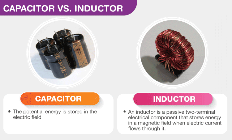
The main differences between Capacitors and Inductors are discussed considering several features such as the current flow, calculation of saved energy, the fundamental definition, their behavior in both DC and AC diagrams, their unit, the difference in the forms of capacitors and inductors, their resistance to various modification in applications, and the relationship between current and voltage.
Regardless of the differences between capacitors vs. Inductors, two of the most broadly utilized electronic instruments are inductors and capacitors. Both are constructed to save energy and perform as fundamental energy resources. However, if you want to know what makes them different, this post presents you with a clear comparison between them to explain Capacitor vs. Inductor completely.
Introduction to Capacitor vs. Inductor
Capacitors and inductors are special kinds of passive components that save and send energy into the circuit but do not use it. Both of the instruments are mainly employed in particular applications related to AC setups, particularly in signal filtering. The considerable difference between the capacitor and inductor is that capacitor is related to dV/dt (the abrupt change in voltage), while the inductor is related to dI/dt (the abrupt change in current).
In addition, capacitors save energy based on the electric field (1/2CV2), while inductors store energy based on the magnetic field (1/2LI2). This post is presented to show the fundamental differences between inductors and capacitors according to units, types, applications, etc.
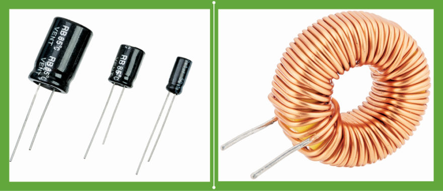
The capacitor and inductor are electrical instruments employed to detect variations in current in the electrical circuits. These devices are passive elements, which employ power from the system, and then discharge it. The applications of both instruments are generally utilized in alternative current and signal processing.
The basic difference to identify the capacitor vs. inductor is that an inductor is employed to apply the energy depending on a magnetic field, while a capacitor operates based on the electric field. This link presents the important features of two physical effects that are used in electrical circuits to demonstrate the Capacitor vs. Inductor clearly.
What are a Capacitor and an Inductor?
The capacitor is an electrical instrument that is constructed from two particular conductors covered by insulators. An electric field is created and electric charges are saved when a potential variance is presented to both terminals. The capacitors are typically used to design electronic systems according to their properties.
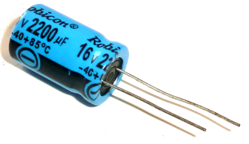
Some of the common dielectric substances used in their construction are Mylar, Teflon, mica, porcelain, and cellulose. A capacitor is introduced according to the material selected like a dielectric or electrode. The dielectric substance is generally applied to help in storing electric power. The capacitor’s amount can be evaluated by the position of the two terminals, their size , and the type of materials used.
Capacitors and Capacitance
Capacitance shows itself wherever a conductive substance is divided by an insulating cover. Capacitive formats can save energy as the electric field; when a capacitive structure is modeled as the electrical section that has a particular value of capacitance, it is introduced as a capacitor.
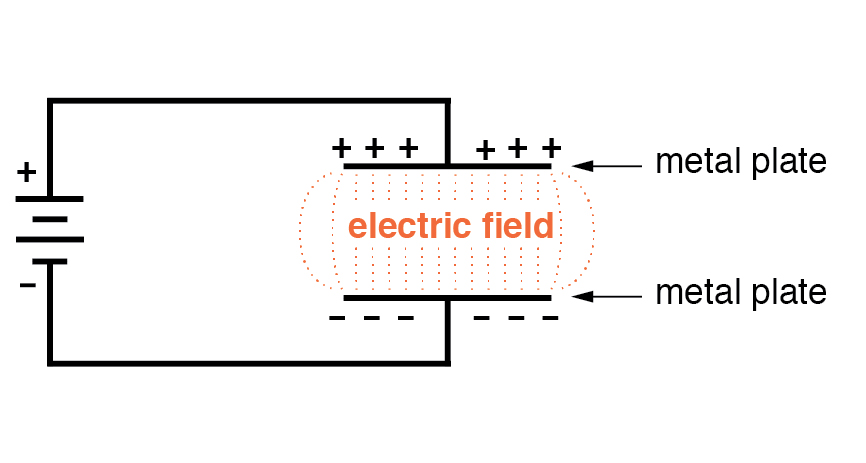
We utilize the charging and discharging for capacitors to detect, respectively, a condition in which the instrument is obtaining power and a state in which the device is providing power. As presented in the figure, we can charge the instrument using a battery. The voltage forces the current to move, and this current provides an electric charge for the capacitor.
The value of charge forms a voltage within the capacitor that immediately increases when the current flow in the circuit reduces. If the capacitor is disconnected from the source and connected to an instrument like a resistor, it operates as an alternative source due to the saved energy in the electric field. It can transform accumulated storage into a usable charge or electric current.
The voltage and current are related together and their behavior can be evaluated by the curves in the next figure. It should be considered that the time axis is based on the “RC” method; this uses the RC time coefficient: a value of time that is related to the capacitance value of a capacitor improved by the resistance in a series arrangement.
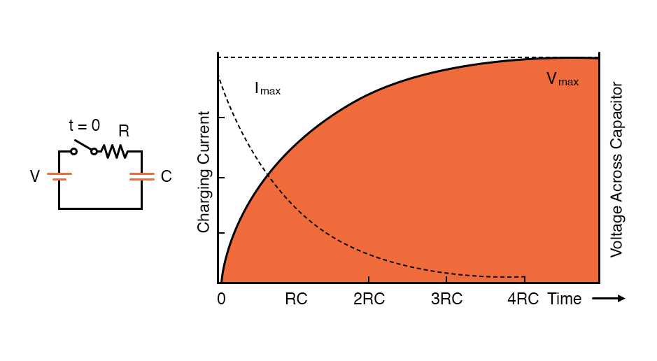
The capacitance of a device is a noticeable parameter of designing a circuit because it can affect the rate of voltage or current variations during the charging process or discharging. More capacitance means that the voltage in the capacitor increases too slowly when it is in the charging process and reduces slowly if it is in the discharging step.
Inductors and Inductance
If you have some information about the main concepts of capacitance, it can generally help you for understanding inductance, because these two effects are very similar, even though they can be introduced as “equal but opposite” phenomena. For instance, A capacitor saves power based on the electric field, but an inductor operates according to the magnetic field.
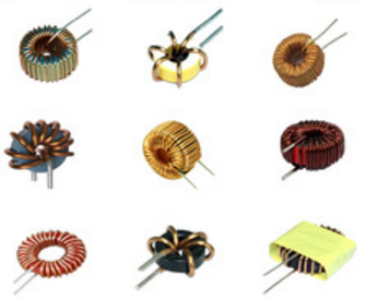
An inductor is a particular choke or coil which has a two-terminal structure and is utilized to build different circuits. The basic performance of an inductor is the energy stored in the magnetic fields. It includes a wire, typically assembled as a coil. If current moves within this coil, it can be stored in that coil.
A perfect inductor operates like a short circuit to direct the current and provide an alternative force that is based on the frequency of the current. The condition of a current flow of an inductor is proportional to the frequency of that current through it. These instruments are introduced as “Coils” because most of their construction is modeled based on the section of the wire and coil. The next figure shows the structure of magnetic field lines clearly.
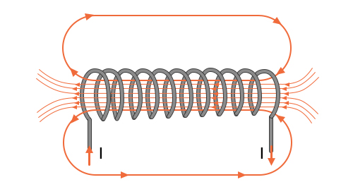
When a capacitor is combined with a voltage source, its voltage can increase, so its current gradually reduces; when an inductor is attached to a voltage supply, its current rises and its voltage gradually drops.
The rate of charging and discharging is determined by the RC time coefficient with a capacitor, but we employ the RL time constant with an inductor, and the inductance (L) can be improved by the resistance arrangement in a series format.
When the inductive circuit is disconnected from the power source, the inductor can generally save the current. It can be said that capacitors resist variations in voltage and inductors resist modifications in the current.
All conductors, including component pins and wires, consist of inductance. To form an inductor, we utilize particular techniques that improve the magnetic field and increase inductance immediately. A complete inductor is a twisted wire simply.
Difference between Capacitor and Inductor
To contrast Capacitor vs. Inductor, we should consider different aspects as mentioned below:
Capacitor Uses
- Capacitors with high-voltage electrolytic can be used in power industries.
- The axial electrolytic capacitors are employed in lower voltage applications of smaller sizes where great capacitance values are required.
- Disk ceramic capacitors that have high voltages, small sizes, and special capacitance are suitable for applications with particular tolerance features.
- The Metalized Polypropylene type of capacitors has good reliability and small size and is desirable for values up to 1µF.
- The surface mount capacitors are relatively high values suitable for various applications covering several layers. They operate as a parallel arrangement of numerous capacitors.
Inductor Uses
Inductors are extremely employed in AC applications such as radio, TV, etc.
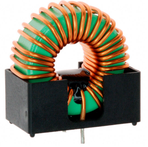
- Chokes: The fundamental feature of an inductor is used in power source circuits where AC provides supply management to be modified to a DC source.
- Energy store: It is utilized to design the spark that provides fire of petrol in automatic engines.
- Transformers: Inductors with a particular magnetic value can be employed to create a transformer.
Unit of Measurement
The value of capacitors is detected in Farads introduced by F. It can be evaluated based on Ampere per second Volt. Because the Ampere is equal to the Coulomb second, it can be said that F = CV.
Otherwise, the inductance is the value of the inductor and it is calculated in Henries (H). Generally, it is the SI unit of this value and is based on the Volt per second Ampere.
Types of Capacitors and Inductors
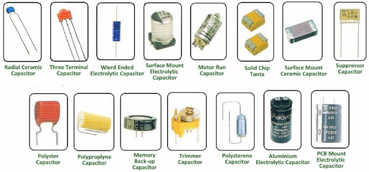
The main types of capacitors are categorized into three forms; tantalum, ceramic, and electrolytic.
The main kinds of inductors are sorted into four types; including coupled inductors, multilayer inductors, ceramic core inductors, and molded inductors.
Relationship between V & I in Linear Circuit
- Voltage shifts behind Current in a capacitor by π/2
- Voltage shifts forward Current in an inductor by π/2
Short Circuit
A capacitor operates as a short circuit for alternating current, and the inductor has the same operation for direct current applications.
Characteristics of Capacitor and Inductor
- Capacitors arranged in parallel configuration operate like resistors in a series arrangement.
- Capacitors in series arrangement perform similarly to the parallel configuration of resistors.
- Inductors in series form operate like a series configuration of resistors.
- Inductors in parallel arrangements work such as resistors in parallel forms.
As a result, these are all considerable tips about the features to contrast capacitors vs. inductor completely. We hope that you understand better information from this post. The next diagram will give you a brief comparison between capacitor vs. inductor in a compact form.
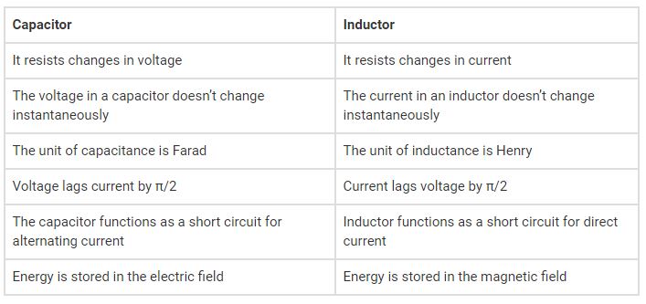
Key Difference Between Capacitor and Inductor
The Key Differences to provide a complete comparison for Capacitor vs. Inductor issue are as follows:
The Capacitor performs similarly to a short circuit in AC systems. The inductor works in direct current circuits like a short circuit. On the other hand, capacitors perform as an open circuit in DC systems to the steady-state situation, while inductors show the short circuit condition to the steady situation in DC circuits.
Energy saved in capacitors is evaluated based on voltage, and 1/2CV2 formula according to the electric field. Whereas power stored in inductors can be calculated according to the current, magnetic field, and 1/2LI2 equation. Capacitance is identified with Farad unit (F), while Inductance is determined in Henry (H).
The current is more than the voltage by 90 degrees in the AC system for capacitors and lags voltage by 90o in the inductors. In their internal structure, capacitors resist the voltage variation while inductors resist the current modifications.
There is no current flow within the plates of capacitors, but current can pass through the coil in the inductors. Capacitors perform as special insulators for DC devices, while inductors operate as a conductor in a DC circuit.
In the system with an inductor, when it is combined with a series arrangement of resistors, the amount of current is low at the start section but it will increase gradually with time. However, when the capacitor is combined in a series configuration with resistors in a DC diagram, the current immediately become great but it falls to 0 later.
Buy Equipment or Ask for a Service
By using Linquip RFQ Service, you can expect to receive quotations from various suppliers across multiple industries and regions.
Click Here to Request a Quotation From Suppliers and Service Providers
Read More on Linquip
- Difference Between Resistance and Impedance- Resistance vs. Impedance
- Principal Difference Between Active and Passive Filters
- Difference Between Condenser and Capacitor in a nutshell 2021
- What is a Polarized Capacitor
- What is Ceramic Capacitor: compact in size with great charge storage
- What is Film Capacitor? Different Types & Working

