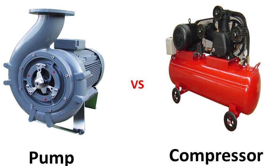
The difference between a pump and a compressor is related to the type of fluid that these two machines are used to transfer from one point to another. Both pumps and compressors are components of fluidic transmission systems. The pumps are devices in which external mechanical energy (operation of the drive machine) is converted into working fluid energy. On the other side, in compressors, the mechanical energy is transformed into the energy of compressed air.
In this article, a complete comparison is made between the operation, construction, features, and types of pumps and compressors.
Difference between Pump and Turbine in Definitions
Transferring fluid through a system needs either a pump or a compressor. These machines achieve this goal but via different operations. Pumps can move liquids or gases, while compressors only move gas due to its capacity to be compressed. A common feature of the pump and turbine is that they both increase fluid pressure.
Pump
A pump is a hydraulic machine that transfers mechanical energy from the motor to the fluid that passes through it. Pumps are used to move incompressible fluids of different densities and temperatures, which can be pure or mixed with solid substances, with different chemical properties ranging from neutral to aggressive.
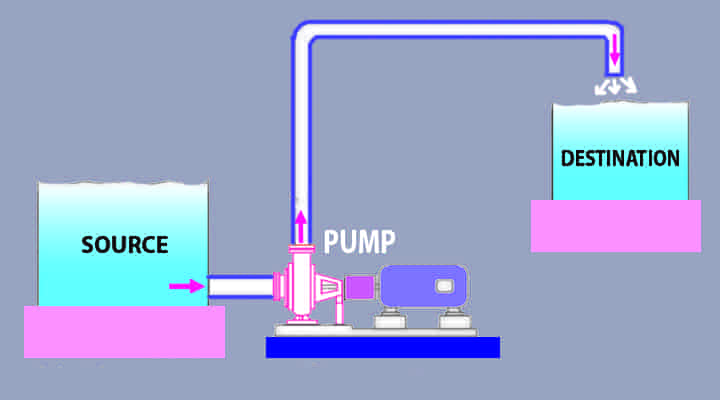
Electric motors are usually used to run the pump, and in the case of mobile hydraulics, internal combustion engines can be applied. Pumps fall into two basic categories: Positive displacement pumps and dynamic pumps such as centrifugal turbopumps. Positive displacement pumps increase the pressure and move the fluid by decreasing the chamber volume in the pump. Positive displacement pumps are used for almost small flow rates. However, turbopumps provide power to the fluid in the rotor by giving pressure force to the fluid using the moving blades. Turbopumps are utilized for relatively high flow rates.
Compressor
A compressor is a mechanical machine that increases gas pressure by reducing its volume. Some compressors can be arranged in a staged structure, meaning that the fluid can be compressed several times in successive stages to increase outflow pressure. Often, the second stage is smaller in size than the first stage so that it can hold the compressed gas without decreasing its pressure. Each stage compresses the gas further and increases its pressure as well as its temperature if the intercooler system is not used between stages.
The compressors can be classified into positive displacement compressors and dynamic compressors. The first type is used almost exclusively in the pneumatic industry. They work based on a variable volume operating chamber, such as the system of a cylinder with a piston. Reducing the volume of the chamber decreases the volume of air inside it and consequently causes an increase in air pressure. The dynamic compressors are further divided into centrifugal and axial types.
Difference between Pump and Compressor in Operating Parameters
Pumps and compressors, as two technical units, have wide characteristics. However, a number of them can be distinguished as basic ones. These values determine the range of application of the unit and are the basis for calculations and selecting the equipment for a specific goal. Other characteristics are secondary and depend more on basic values. Secondary characteristics also affect the design, operation, and efficiency of the machine, but to a much lesser extent.
Primary parameters determine the working conditions of a pump or compressor. What unit is suitable can be found based on a limited set of parameters. The choice may be made based on a single primary parameter or a set of ones depending on the needs.
Pump
The basic operating parameters for pumps are:
Flow Rate
Flow rate is expressed in two ways: volume rate in cubic meters per second (m3/s) or mass rate in kilograms per second (kg/s).
Head
The head of a pump (in meters) is the height it can deliver. Its value shows how much pressure the pump can add to the fluid.
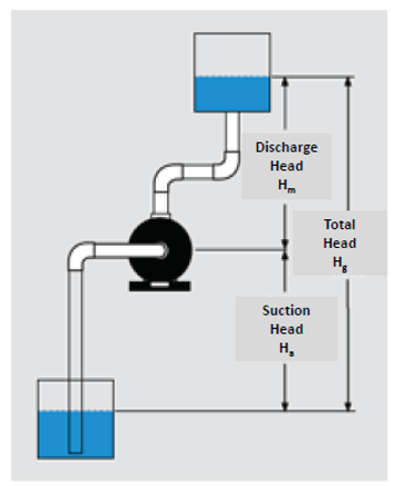
The head of a pump is given as follows.
H=H_g+Y
and
H_g=H_a+H_m
Hg is the geodetic head as the difference of levels between the delivery tank and the suction line. Ha (geodetic suction height) is the difference between the level of the pump axis and the sucked liquid surface. Also, Hm (geodetic delivery height) represents the difference between the pump axis height and the tank level to which the liquid is delivered. Y shows the head loss due to the friction and the presence of narrowing curves and so on.
Specific Speed
Specific speed is an indicator used to predict a turbopump’s performance. It predicts the overall shape of pump impellers to find the flow and head characteristics in order to select the most appropriate pump for a specific application. Knowing a certain specific speed leads to calculating the basic dimensions of the unit components easily.
The specific speed of a pump is a dimensionless number defined using the following relation:
N_s=\frac{n\sqrt{Q}}{\left(gH\right)3/4}
Here n, Q, and H are pump rotational velocity (in radian per second), flow rate, and hydraulic head of the pump, respectively.
Specific Work
The pump gives energy to the fluid by delivering work. The specific work of a pump is defined as work per unit weight of fluid in Joules per kilogram (J/kg), which can be expressed by the following equation:
w=\frac{p_2-p_1}{\rho }
p and ρ are fluid pressure (N/m2) and density (kg/m3), respectively.
Output Power
Pump output power (in watt) is defined as useful work delivered by the pump. It can be expressed by the following equation:
P_{out}=\rho gHQ
Efficiency
Pump Efficiency (%) is the ratio of pump output power to input power. The input power of a pump (in Watt) is the mechanical power taken by the shaft.
\eta =\frac{P_{out}}{P_{in}}
Compressor
The use of a compressor is usually affected by the following characteristics:
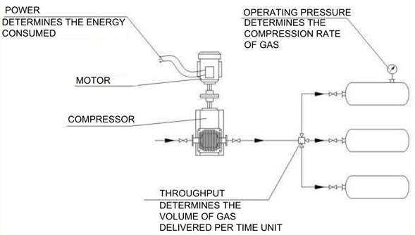
Operating Pressure
The pressure produced by a compressor is often measured in Pascals (Pa), bars (bar), or atmospheres (atm). Operating pressure is divided into gage pressure (Page) and absolute pressure (Pabs), which are related by the following equation:
P_{abs}=P_{gage}+P_{atm}
Patm is the atmospheric pressure.
Depending on the pressure generated by the compressors, they are classified into the following units:
- Vacuum (0.05 MPa)
- Low pressure (0.15 MPa to 1.2 MPa)
- Medium pressure (1.2 MPa to 10 MPa)
- High pressure (10 MPa to 100 MPa)
- Ultra high pressure (more than 100 MPa)
Flow Rate or Throughput
Compressor flow rate is the volume of gas delivered per unit of time. It is measured in m³/min, liter/min, m³/h, or other similar units. Compressor flow rate is determined for both suction and discharge lines, which are not equal because of a change in cog volume in the process of combustion. For inlet flow, standard conditions are usually considered, including atmospheric pressure and temperature of 20°C. Based on the flow rate, compressors are classified into the following three categories:
- Low flow rate units (up to 10 m³/min)
- Medium flow rate units (10 m³/min to 100 m³/min)
- High flow rate units (more than 100 m³/min)
Compressor Power
The power of a compressor is a product of the flow rate of gas multiplied by compression energy. This is called theoretical power and is calculated by the following equation:
N_t=\frac{Q\rho A}{1000}
where Nt, Q, ρ, and A are theoretical power (kW), flow rate (m³/min), gas density (kg/m3), and theoretical gas compression energy (J/kg), respectively.
Certain sets of equations can be applied to calculate gas compression energy for different compressor types. Usually, for a single-stage compressor, it is given by the following relation:
A=h_2-h_1
h1 and h2 are gas enthalpy (J/kg) before and after the compression, respectively. If compression is conducted in multiple stages, then the value of (h2-h1) in the formula must be replaced by the sum of each delta for different stages. If the compression energy is identical for each stage, the equation for the n-stage compressor is as follows:
N_t=\frac{Q\rho n\left(h_2-h_1\right)}{1000}
Efficiency
Not all the power provided to the compressor is converted to useful power, and parts of it are wasted for various reasons. Hydraulic losses, leakage losses, and mechanical losses such as those related to shaft rotation in centrifugal compressors reduce compressor efficiency. Therefore, the compressor efficiency is calculated as follows:
\eta ={\eta }_h{\eta }_v{\eta }_m
The terms ηh, ηv , and ηm are hydraulic, volumetric, and mechanical efficiencies, respectively. In a closer look we have:
{\eta }_h=\frac{N_i}{N_t}
in which Ni is called indicative power.
{\eta }_v=\frac{N_u}{N_i}
where,
N_u=Q_aVp
Qa, V, and p are the actual flow rate, head, and average pressure before and after compression, respectively.
{\eta }_m=\frac{N_s}{N_u}
Ns is compressor output power that is applied on the shaft in centrifugal compressors.
Difference between Pump and Compressor in Classifications
Pumps and compressors are classified as follows based on the structure of the machine and how the energy is exchanged with the fluid.
Pump
Two major types of pumps are positive displacement pumps and centrifugal pumps.
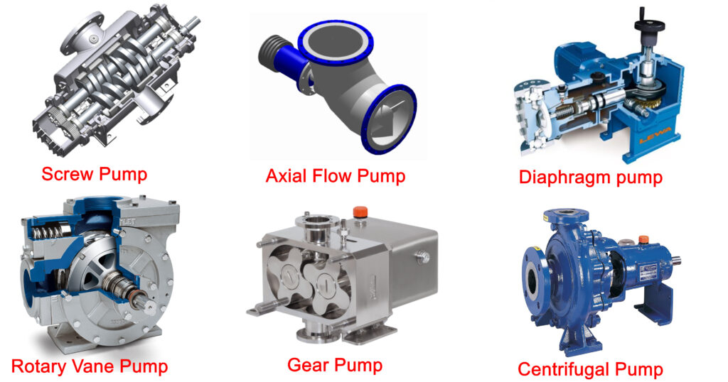
Positive Displacement Pump
Positive displacement pumps transfer fluid by displacing and forcing a certain amount of fluid into a discharge pipe. Regardless of the discharge pressure that causes them to be constant flow machines, they can supply the same flow at a certain speed. Positive displacement pumps usually have a relief or safety valve on the discharge side to prevent the line from bursting.
Suppose a positive displacement pump works against a closed discharge valve. In that case, the pressure inside the discharge will increase, causing a line to burst that will damage the pump. Positive displacement pumps are classified into reciprocating pumps (piston plunger, diaphragm, and rotary pumps, including gear, lobe, screw, regenerative or peripheral, progressive cavity, and vane), and dynamic pumps like centrifugal pumps.
Reciprocating Pump
A reciprocating pump consists of a cylinder and a plunger in which the retract stroke makes suction valves to draw fluid into the cylinder. The forward stroke forces the liquid to flow into the discharge valve.
If only one cylinder is utilized, the flow of fluid alters between the maximum level in the middle position to the zero level at the end positions. By using two or more out-of-phase cylinders together, notable energy losses are overcome. In contrast, diaphragm pumps which are typically used for hazardous and toxic fluids, pressurize the hydraulic oil through the plunger, which bends the diaphragm in the pumping cylinder.
Rotary Pump
In a rotary gear pump, the space between gear teeth and the pump chasing on the suction side traps the fluid. When the two gears’ teeth are rotated against each other, the pressurized fluid comes out on the pressure side. Common uses of gear pumps include chemical installations. They are usually used to pump high viscosity fluids.
Lobe pumps work like gear pumps, except that the two lobes driven by external timing gears are controlled so that they never have contact.
A progressive cavity pump employs a metal rotor that rotates inside an elastic stator. Progressive chambers form between rotor and stator from suction end to the discharge end as the rotor turns, so the fluid moves.
Dynamic Pump
A centrifugal pump turns input power into kinetic energy by accelerating liquid using impellers. Centrifugal pumps are machines with constant heads. A volute pump is the most typical centrifugal pump in which the fluid enters the pump from the eye of the impeller spinning at a high rotational speed.
As the fluid accelerates outward the chase of the pump radially, a vacuum is created at the eye of the impeller. This vacuum causes more suction and more fluid to enter the pump. The maximum head is determined by the pump impeller’s outer diameter and the rotational speed of the shaft.
To estimate the kinetic energy of a centrifugal pump, the term head is used. Head is the height of the liquid column that the pump can produce from the pump energy. Since the pressure can change with a specific gravity change, the head is used to measure energy instead of pressure.
If the shaft rotates at the same speed (in rpm), a pump will transfer to the same height regardless of the type of fluid. The only difference is the power required to pump different fluids types. Usually, the higher the specific gravity, the more power is needed.
The relation between the developed total head and pressure difference through the pump as well as the velocity at the pump outlet is given as follows:
\mathit{\Delta}h=\frac{p_2-p_1}{\rho g}+\frac{v^2_2}{2g}
Compressor
There are different compressor types that transfer air into a chamber. Most compressors are of positive displacement type in which, by pushing air into the chamber, volume is reduced to compress the air. Reciprocating or piston-type compressors move air into the cylinder chamber using pistons and one-way valves.
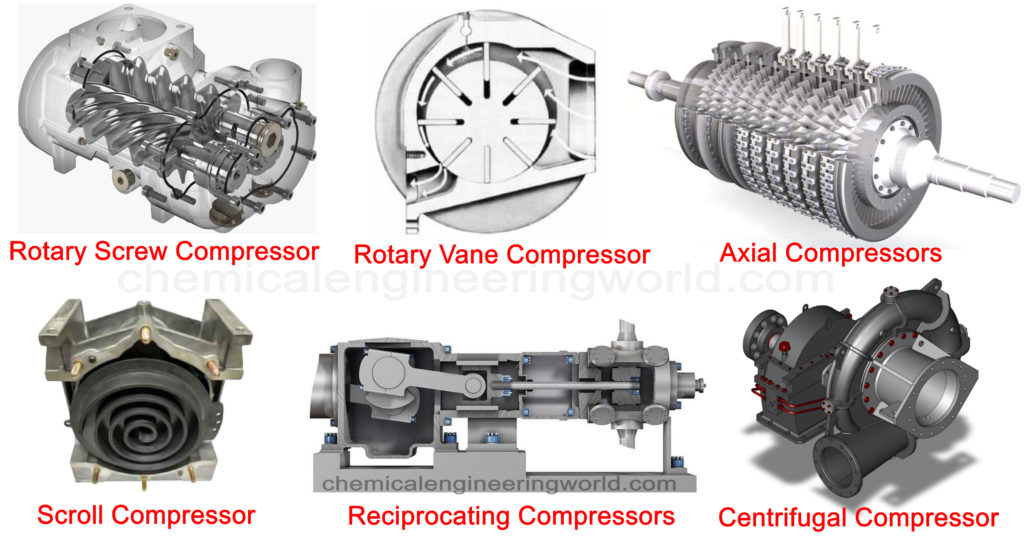
Most compressors available on the market are either one or two-stage compressors. Single-stage compressors operate for pressure ranges from 70 to 100 psi. For larger pressures between 100 and 250 psi, two-stage compressors are common. Single-acting compressors work with only one side of a piston, and double-acting compressors use both sides. Compressors have pressure limits that shut off when the pressure is reached. The air is stored until it is used for a kinetic energy application.
Compressors convert power taken from an electric or gas-powered motor into potential energy in the form of pressurized air. The compressor stores air into tanks, increasing the pressure.
Rotary-screw compressors apply helical screws to lead the air into the chamber. The performance of the screw is the same as that of the piston by displacing and compressing air. The most well-known rotary-screw compressors are of single-stage helical or spiral-lobe oil-flooded screw types. These compressors work without valves and are oil-cooled. The oil is used to seal the internal clearances. Because the cooling takes place inside the compressor, the working temperature does not reach extreme temperature levels.
Rotary screw compressors cause some heat damages due to friction. Effective use of rotary screw compressors needs regular compressor cooling.
Dynamic compressors are usually centrifugal compressors. Applying a rotating impeller, a centrifugal force is created to accelerate or decelerate taken air, which makes it pressurized. To handle the capacity of a centrifugal compressor, its inlet guide vanes are set adjustable. The volumetric flow reduces by closing the guide vanes, so does the capacity.
Difference between Pump and Compressor in Components
It is not easy to describe all the constructional differences between pumps and compressors because there are tremendous diversities within each machine. Both are categorized based on the working principles, applications, fluid types, and so on.
Pump
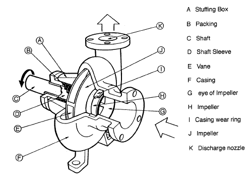
Basic components of a pump usually include the casing or housing, impeller, volute, motor, and shaft.
Compressor
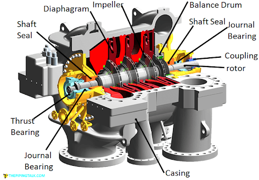
Compressors typically consist of a motor, storage tank, valves, drain, intake filter and so on.
Difference between Pump and Compressor in Applications
Pumps and compressors are among the most widely used machines in different industries, technological constructions, factories, larger plants, and almost every household.
Pump
The most common use of domestic pumps is in the washing systems where they work to discharge the water out of the device in the sewerage system. Cars, airplanes, and ships also utilize pumps in cooling, oil, and fuel applications.
Many industrial plants have pumps for various purposes such as irrigation, mining, air conditioning, refrigeration, and so on.
Compressor
Compressors are often used in refrigeration technology (refrigerators, air conditioners, and showcases). Furthermore, they have applications in the processing industry like refineries, technical gas plants (O2, N2 bottles), and pneumatic tools and automatics, including shipbuilding, construction, vehicles (brakes and doors).
Difference between Pump and Compressor in Fluid Physical Changes
As changes in fluid energy are made by the pump or compressor, changes in their physical properties may also occur.
Pump
The volume of fluid is not changed from inlet to outlet of the pump. Besides, a pressure change does not occur necessarily.
Compressor
It works based on a pressure change, and therefore, the volume of gas changes.
Read More In Linquip
- Different Types of Hydraulic Pumps: a Complete Guide
- Difference Between Pump and Motor
- Difference Between Pump and Turbine
- Different Types of Pumps: Ultimate Guide in 2021
- What Is the Difference Between a Single Stage and Two Stage Compressor?
- The 8 Best Small Air Compressors
- Difference Between Air-Cooled vs Water-Cooled Compressor
- The 7 Best Air Compressors of 2021
- The 10 Best Air Compressor for Home Garage in 2021
- The 10 Highest CFM Air Compressors in 2021
- A Cheat Sheet For The Types of Pump Couplings
- Types of Centrifugal Pumps: All Classification & Working Principles
- The Differences Between Axial Compressor & Centrifugal Compressor
- Top Air Compressor Suppliers & Manufacturers In The World
- The Essential Guide to the 4 Types of Air Compressors
- Reciprocating Compressor: Introduction, Efficiency & Types
- Optimize Your Pump System with Linquip’s Pump Flow Rate Calculator

