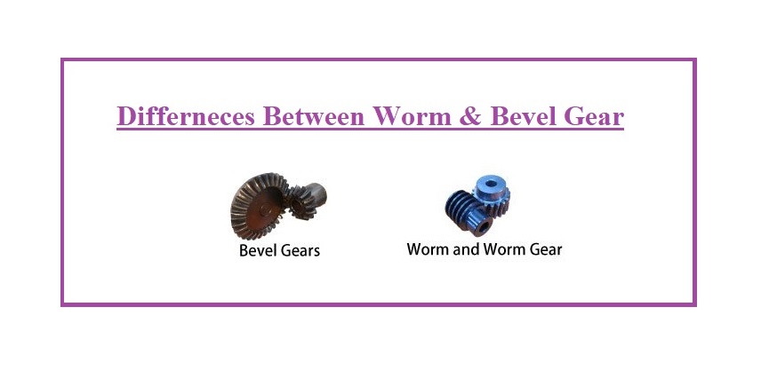
Differences Between Worm and Bevel Gear- Choosing the worm gear units or bevel gear types has an important influence on operating costs and efficiency in industrial applications. We would like to give you the most considerable advantages of worm and bevel gear units in this post so that you can know which one is the most appropriate for your application. But first, we should clearly explain what the gear is.
What is a Gear?
A gear is a typical kind of machine element in which teeth are cone-shaped surfaces or cut around cylindrical with the same spacing. They are utilized to transmit forces and rotations from the main shaft to the driven shaft by meshing a pair of these components. Gears can be categorized by shape as cycloidal, involute, and trochoidal gears. Also, they can be divided by shaft positions as intersecting shaft gears, parallel shaft gears, and non-intersecting and non-parallel shaft gears. The gears’ history is old, and the usage of gears already appears in ancient Greece in B.C. in the manuscripts remained of Archimedes.
There are many kinds of gears such as spur gears, helical gears, bevel gears, worm gears, gear racks, etc. These can be broadly classified by looking at the positions of axes such as parallel shafts, intersecting shafts, and non-intersecting shafts.
It is vital to know exactly the differences between the gear types to accomplish necessary power transmission in mechanical applications. Even after selecting the best type, it is essential to think about factors such as standard of precision grade (DIN, ISO, AGMA), dimensions (number of teeth, module, face width, helix angle, etc.), allowable efficiency and torque, need for heat treating and/or teeth grinding, etc.
In addition to the sections below, each part, such as worm gear, bevel gear, rack, and pinion, etc. has its additional post regarding the respective gear form. You can visit it completely in our other posts.
It is suitable, to begin with the general knowledge of the forms of gears as presented below. But in addition to these, there are other types, including herringbone gear (double helical gear), face gear, hypoid gear, crown gear, etc.
Frequent Applications of Angular Gearboxes
Worm and bevel gears are typically employed to transfer power at right angles or when other properties are needed, including:
- Mixer
- Conveyor belts
- Elevators
- Crane
- Many other applications
What is a Worm Gear?
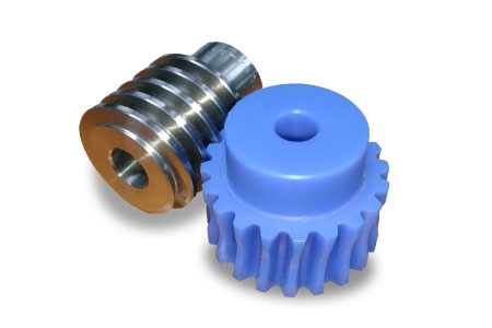
A worm gear unit has two main components: a worm wheel and a worm shaft with worm gears. The two parts are always constructed of two different materials (bronze worm wheel and steel worm shaft). Worm gears transfer the movement load at right angles within a sliding effect instead of a rolling motion.
Advantages of Worm Gears over Bevel Gears
Worm gears are generally utilized when a large gear ratio is needed. A large overall ratio can be obtained by a worm gear unit with just a few stages. This means that a less expensive and smaller gearbox can be used. The greatest ratio of a worm gear type is about 100:1.
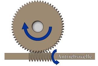
High self-locking based on the sliding result of the worm shaft makes an extra brake either obsolete, or it is just necessary to set a less expensive, small brake. However, this feature is based on the friction angle and the angle of inclination.
Other differences between worm and bevel gear that make them more useful are:
- They are more favorable than bevel gears in industrial applications
- They are possible to employ hollow shafts
Disadvantages of Worm Gears
The sliding touch of the gears results in heavy friction in the system, which causes:
- High-performance temperature
- Low efficiency
- High wear on the worm wheel, which is commonly constructed of bronze. (Just through bronze construction, relative efficiency is feasible. The friction would be much greater with steel on steel).
What is a Bevel gear?
We should present 4 types of bevel gears to know them clearly:
- Spiral
- Straight
- Zerol
- Skew Tooth
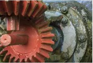
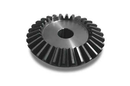
Bevel gear units contain two main components, the pinion, and the gear, which transform movements at right angles.
Bevel gears use angular gear teeth. As the gears turn, the entire tooth width of the interlocking teeth is employed to transmit the force. In addition, several teeth contact at the same time. This results in the following advantages.
Advantages of Bevel Gears over Worm Gears
- Increased torque potential in comparison with worm gears of the same size.
- Low-performance noise (quiet performance is especially advantageous in environments such as airports or theatres).
- The best efficiency (rolling of bevel gears is very effective in comparison with the sliding effect of worm gears (98.5%)).
- The metal teeth of bevel gears never come into direct touch with an oil film.
- They are possible for using hollow shafts in particular applications.
Disadvantages of Bevel Gears over Worm Gears
- Bevel gears are constructed in pairs. As a result, both gears must be replaced for repair and maintenance.
- They are not cost-effective.
- Bevel gear units should be positioned exactly to obtain high efficiency, so the shafts should be installed very precisely.
- They have a limited translation range, i.e. the maximum rate of 6:1 per bevel gear unit. Adding spur gear sets are essential to obtain a higher overall gear rate.
- Bevel gears are not suitable to reduce high-speed cases. At high speeds, a bevel gear set creates a lot of noise.
What are the Main Differences Between Worm and Bevel Gear?
If we want to know the differences between worm and bevel gear, we should primarily learn the ways to employ gears in mechanical design conditions. Visit here to explore more about them.
Gears are fundamentally employed to transmit the motion of power, but based on some concepts, they can be employed as machine elements in different methods. Below are introductions to some of the methods.
Grasping Mechanism
Using two bevel gears of the same diameter in mesh so that once the driver gear is converted, the next gear is also turned. You can achieve a working piece grasping mechanism by employing this movement. Workpieces of different sizes can be obtained by regulating the opening angle of the grasping claw causing a versatile grasping mechanism model.
Intermittent Motion Mechanism
The intermittent motion mechanism is also known as the Geneva mechanism. While according to the requirement for the specialized mechanical elements, it is not cost-effective for bevel gears. A low price and easy intermittent mechanism can be achieved by using the missing teeth gears.
We mean a gear in which any number of gear teeth have been eliminated from their roots by missing teeth gear. The gear that is mounted to the missing teeth gear will turn as long as it meshes together but will cease as soon as it encounters the missing teeth part of the main gear. However, it has the drawback of shifting once an external load is applied while the gears are detached. In these applications, it is vital to keep its position by means such as employing a friction brake.
Special Power Transmission Mechanism
By joining a one-path clutch (a configuration that permits rotational movement just in one direction) in a single stage of a gear set in a speed reducer, you can make a mechanism that transforms power in one direction but stops in reverse in worm gears.
By employing this method, you can make a configuration that performs a motor when the electric energy is on, but when the energy is cut, it moves the next shaft by a spring load.
The speed reducer is performed as the spring is wound by internally combining a spring (spiral spring or torsion coil spring) that winds in the rotational path in a gear set. When the spring is perfectly wound, the motor is ceased, and the electromagnetic brake joined with the system holds this place.
Once the electricity is cut, the brake is unleashed, and the spring load will run the gear in the opposite direction to when the motor was running. This method is employed to close valves when the energy is lost (emergency conditions) and is introduced as “spring return from an emergency state of the shutoff valve”.
Why is it Difficult to Obtain Needed Gears?
Discussion of the differences between worm and bevel gear is too complex since there is no standard for the gear itself.
Gears have been employed worldwide since ancient times in several cases and are indications between other parts of machine elements. Although as far as the precision class of gear types, there are industrial norms in different regions such as DIN(Germany), AGMA(US), JIS(Japan), etc.
Otherwise, there are no norms about features that eventually determine [the gear itself], including its size, form, material, bore diameter, hardness, etc. In conclusion, there is no certain approach, but it is an accommodation of the actual gear characteristics decided by the individual constructors that suit the model of their systems or those chosen by the individual gear designers.
There is a diversity of gear features. As explained above, there is a diversity of gear properties. Except for too simple gears, it is not an overestimation to present that there are as several forms as there are cases where gears are employed.
For instance, among different gears, when the tooth pitch, pressure angle, and the number of teeth features are matched, other properties identify a gear such as the face width, bore size, final hardness, heat treatment, the existence of shaft, surface roughness after grinding, etc. It can be said that the possibility of two gears being matched is too low. This is one of the reasons why it is problematic to gain replacement gear (for example, when the gear breaks).
Cannot Obtain the Desired Gears
Sometimes it happens that you cannot gain replacement gear for a broken or worn-out one at the place the system is being used. Most of the time there is no problem in this case if there is a manual or a components list for the system that includes the drawing necessary for the gear’s designer. There is also no issue if it is possible to contact the machine’s constructor and if the manufacturer can provide the required gear. Unfortunately, in many cases:
- The system’s manual does not present the drawing of the gear by itself
- It is not feasible to gain only the gear from the system’s manufacturer, etc.
For such matters, it is problematic to gain the required gear. In these applications, it becomes essential to make the producing drawing of the broken part. This is always difficult without professional technical gear knowledge. The condition is always similarly difficult for gear constructors based on insufficient information for the gear. Also, making the drawing from the broken part needs a great deal of engineering manpower, and this made the question of who will be burdened with this price.
When just one particular gear is required, the production price is too high. When the system using gear is mass generated, then so is the gear that is constructed to a particular production lot size, spreading the set price of the gear by taking advantage of the economy of scale.
Otherwise, consumers utilize the system after it has been constructed, and when one or two gears require replacement, they always face a great production cost making the ultimate repair cost at times very expensive. In short, the difference in the two construction ways (small lot production and mass production) has a considerable effect on the price of the gear.
For instance, a purchase of 300 gears in one shot for a new project like machinery production (creating 300 gears in one lot) compared to using one replacement gear later (with the construction lot of 1 piece) has a massive difference in production unit cost. This is the same condition at the design stage of a new system when one gear is required for the prototype with the same great cost.
Possibility of Using Standard Gears
When modeling a modern machine, if the features of the gears employed can be matched to those of the gear constructor’s standard gears, the issues mentioned above can be revised. By this method:
- You can avoid the step of modeling new gears during the design of a system.
- You can use 3D/2D CAD models, strength calculations, printable component drawings, etc. presented by the gear maker.
Even if you require just one gear as a trial, the normal gears are typically mass-produced by the gear constructor and are advisedly priced. These are some of the conveniences you can take advantage of.
Also, when a gear in a system in use requires a replacement, if its features are similar to those of a gear maker’s, it may be feasible to interchange it with a common part by itself or a normal gear with a secondary function. In this condition also, it may be feasible to prevent the inconvenience of performing the following tasks:
- Create new drawings
- Look for drawings
- Accept the high cost of one-piece production
- Look for a contractor to make the gear
Buy Equipment or Ask for a Service
By using Linquip RFQ Service, you can expect to receive quotations from various suppliers across multiple industries and regions.
Click Here to Request a Quotation From Suppliers and Service Providers
Read More on Linquip

