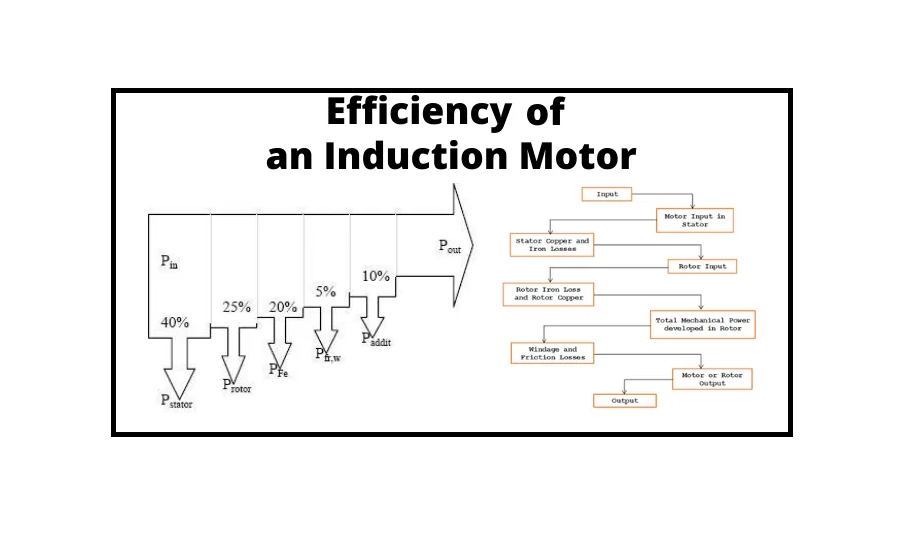
Efficiency of Induction Motor- The analogous circuit of an induction motor can be utilized to assess the machine’s losses and efficiency. The efficiency of induction motor is determined in the same way as it is for any other device. Motor losses have a direct impact on the cost of operation and, indirectly, on the motor rating.
There should be some rotor slippage in relation to the frequency; normally, this is roughly 5%. As a result, these motors are classified as asynchronous. Three-Phase Induction Motors have an efficiency range of 85 to 96 percent. The efficiency of an induction motor is an essential factor to consider while using it. Several Suppliers and Companies, as well as various manufacturers and distributors, have introduced the efficiency of induction motors, and there are many Induction Motors For Sale on Linquip.
There is a complete list of induction motor services on the Linquip website that covers all OEM fleets. Linquip vendors can assist you with this. Please contact Induction Motor Experts in Linquip to learn more about how to connect with a diverse group of service providers who consistently deliver high-quality products.
Measuring losses is a common method of determining efficiency. ANSI, IEEE, NEMA, and the Canadian Standards Association have all specified measurement standards in detail.
Power Transfer Stages of Induction Motor
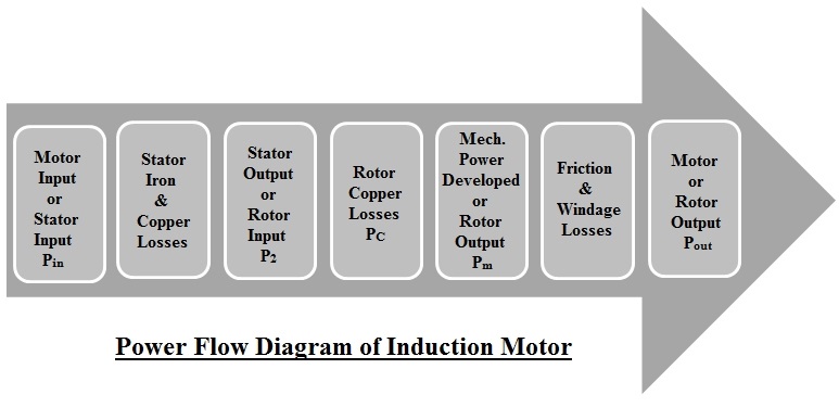
An induction motor turns the electrical energy it receives into mechanical energy. In an induction motor, the multiple phases of this conversion are referred to as power transfer stages. The stator input, or three-phase power input, to an induction motor, is:
{P}_{in}={V}_{L}{I}_{L}Cos\phi
Where VL and IL are the line values of the stator supply voltage and current, respectively, and Cosφ is the motor’s power factor.
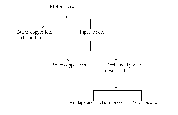
The loss of stator iron and copper consumes a portion of this power. Through the air gap, the remaining power is passed inductively to the rotor. The rotor input P2 is what it’s called. Therefore, P2 is equal to Pin – stator iron and copper losses.
The majority of rotor losses are copper losses, with a little amount of rotor iron loss that is often overlooked. The gross mechanical power developed by the motor Pm is obtained by subtracting the rotor copper losses from P2. So, Pm = P2 – rotor copper losses. Visit here to see the calculation method of the efficiency of induction motor.
Mechanical losses consume a portion of Pm, leaving the remaining power available to the load at the shaft. This is known as the Motor Pout’s Net Output Power. The above stages can be depicted in a diagram called an Induction Motor Power Flow Diagram.

Types of Losses
In a three-phase induction motor, there are two types of losses. These are:
Constant or Fixed Losses
Constant losses are losses that are assumed to remain constant throughout an induction motor’s usual operating range. By running a no-load test on the three-phase induction motor, the fixed losses can be simply determined. These losses are further divided into the following categories:
- Iron or core losses
- Mechanical losses
- Brush friction losses
Iron or Core Losses
Hysteresis and eddy current losses are two types of iron or core losses. The use of lamination on the core reduces eddy current losses. Because the area of the core is reduced by laminating it, the resistance increases, resulting in a reduction in eddy currents. The use of high-grade silicon steel reduces hysteresis losses. The frequency of the supplied voltage affects core losses.
The stator frequency is always f, and the rotor frequency is slip times the supply frequency, (sf), which is always smaller than the stator frequency. Because slip is on the order of 3% under normal working conditions, the rotor frequency for a 50 Hz stator is roughly 1.5 Hz. As a result, rotor core loss is minor compared to stator core loss, and it is often overlooked in normal operation.
Mechanical and Brush Friction Losses
In wound rotor induction motors, mechanical losses occur at the bearing, and brush friction losses occur at the brush. These losses begin at zero and rise as the speed of the vehicle increases. The speed of a three-phase induction motor is normally constant. As a result, these losses are nearly constant.
To explore the relation between rotor output, rotor input, and rotor Copper losses, Let P2 = Rotor input, Pc = Rotor copper losses, Tg = Gross torque developed by the rotor in N-m, and Pm = Gross mechanical power developed or rotor output.
Shaft Torque or Useful Torque Tsh is the actual torque available at the shaft, so Tsh = Gross torque and Tg = Torque lost due to the friction and windage losses.
Now, a revolving magnetic field rotates at a speed of Ns rpm to provide input to the rotor through the air gap. In terms of gross torque Tg and speed, the rotor input can be written as,
{P}_{2}=\frac{2\pi {N}_{s}{T}_{g}}{60}
The torque created is unchanged, but the rotor output, which is the gross mechanical power developed Pm, is now at a speed of ‘N’ rpm. So, on the output side, we may say,
{P}_{m}=\frac{2\pi {N}{T}_{g}}{60}
We know that, rotor copper losses, Pc=P2 – Pm.
Using the above equations, we get
\frac{{P}_{c}}{{P}_{2}}=\frac{{N}_{s}-N}{{N}_{s}}=s
As a result, rotor copper losses are equal to slip times rotor input. Now that total mechanical power has been generated as Pm=(1-s) P2.
As a result, the rotor input multiplied by (1 – s) equals the gross mechanical power developed. So,
\frac{{P}_{c}}{{P}_{m}}=\frac{s}{1-s}
Variable Losses

Copper losses are another name for these losses. Current flowing in the stator and rotor windings causes these losses. The current flowing in the rotor and stator windings changes as the load changes, and so these losses fluctuate as well. As a result, these losses are referred to as variable losses. The copper losses are measured using a three-phase induction motor with a blocked rotor. An induction motor’s primary function is to convert electrical energy into mechanical energy. The power travels through various phases during the conversion of electrical energy to mechanical energy.
A power flow diagram depicts the movement of energy across various phases. The three-phase induction motor’s input, as we all know, is three-phase power. As a result, the stator of a three-phase induction motor receives three-phase power.
A percentage of this power is utilized to compensate for stator losses, which includes stator iron and copper losses. The remaining power is delivered to the rotor as rotor input (input electrical power – stator losses).
Now the rotor must transform this rotor input into mechanical energy, but it cannot convert the entire input into mechanical output since it must supply rotor losses. As previously stated, there are two types of rotor losses: rotor iron loss and rotor copper loss. The iron loss is normally ignored because it is dependent on the rotor frequency, which is relatively low when the rotor rotates. As a result, the rotor only has rotor copper loss. As a result, these rotor copper losses must be supplied by the rotor input. The remaining part of the Rotor input, P2, is turned into mechanical power, Pm, after feeding the rotor copper losses.
The shaft transfers this mechanical power to the load, however, there are certain mechanical losses like friction and windage. As a result, the developed gross mechanical power must be used to compensate for these losses. Thus, Pout is the net output power created at the shaft and finally delivered to the load. (The shaft power, or useable power, is referred to as Pout)
Pout = Pm – Mechanical losses (friction and windage losses).
The rotor’s torque is gross mechanical torque, and because of mechanical losses, the entire torque cannot be used to drive the load. The load torque, also known as shaft torque or useful toque, is the net output torque. Therefore, Tsh=Tg – Tlost.
Where Tlost = Torque lost due to mechanical losses.
Which Induction Motor Has Lowest Efficiency?
HP stands for output horsepower, while PF stands for input power factor. Large three-phase induction motors are, on average, more efficient than smaller motors. At maximum load, large induction motor efficiency can reach 95 percent, but 90 percent is more frequent. When compared to a three-phase induction motor, the single-phase induction motor has a lower power factor. Single-phase motors have poor efficiency, but three-phase induction motors have high efficiency.
Efficiency of Three-Phase Induction Motor

The output-to-input ratio is called the efficiency. The rotor efficiency of the three-phase induction motor is the ratio of rotor output per rotor input which is equal to the Gross mechanical power developed / rotor input or Pm/P2.
Therefore, the three-phase induction motor efficiency is the ratio of the power developed at the shaft per the electrical input to the motor.
Buy Equipment or Ask for a Service
By using Linquip RFQ Service, you can expect to receive quotations from various suppliers across multiple industries and regions.
Click Here to Request a Quotation From Suppliers and Service Providers
Download Efficiency of Induction Motor PDF
Read More on Linquip
- Types of Induction Motor: A Concise and Useful Guild
- What is Speed Control of Induction Motor?
- Efficiency of Wind Turbines
- Efficiency of Electric Motor
- DC Motor Efficiency
- The Only Guide You’ll Ever Need For The Working Principle of Induction Motor
- Efficiency of Induction Motor: Calculation & Equation
- Efficiency of Inverter: Calculation & Equation Guide
- What is Generator Efficiency? Calculation & Formula Guide
- Electric Heater Efficiency and Running Costs
- Efficiency of Fuel Cell: Calculation Formula & Equation
- Space Heater Efficiency For Various Types of Heater
- Heater Efficiency Calculation: Formula & Equation
- Fan Efficiency Calculation: Formula & Equation
- Efficiency of Diesel Generators Calculation: Formula & Equation
- Calculation of Pump Efficiency: Formula & Equation


