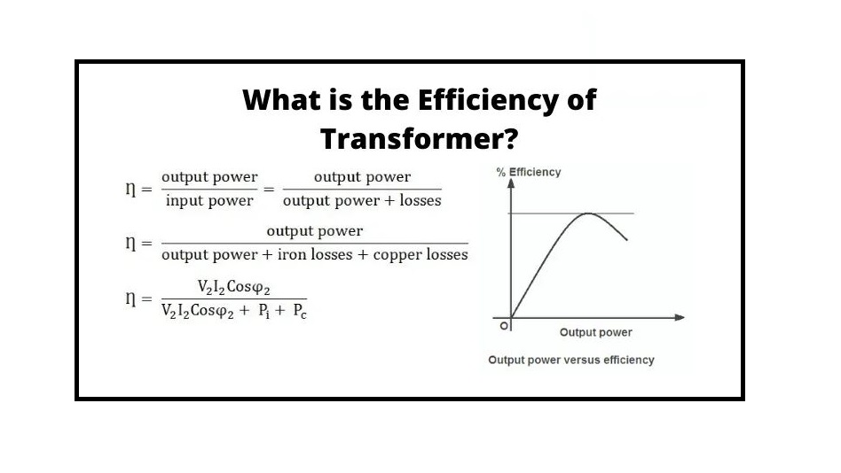
The Efficiency of transformer is introduced as the ratio of beneficial output power to the input one. The input and output power are detected in the same unit and its unit is either in KW or Watts (W). The efficiency of transformer is expressed by η. In this post, we will completely explain this term using its equations and discuss the losses that reduce this efficiency.
All the information you could possibly need about transformer equipment and devices can be found on Linquip’s website. Any questions you might have about transformers can be answered by Linquip’s team of experts. The best place to start learning about transformers is Linquip’s article, “What Is a Transformer?“.
Discover a range of transformer devices & equipment with Linquip’s Transformer Products list. You can also sign up to become a Linquip Transformers Expert and take advantage of all the available features. Have you ever thought about Guest Posting on Linquip? Content can also be submitted as a guest on the Linquip platform.
What is the Efficiency of Transformer?
The Efficiency of transformer is introduced as the ratio of beneficial output power to the input one. The input and output power are detected in the same unit. Its unit is either in KW or Watts (W). The efficiency of transformer is expressed by η. In this post, we will explain this term using its equations, and discuss the losses that reduce this efficiency.
What is the Efficiency of Transformer?
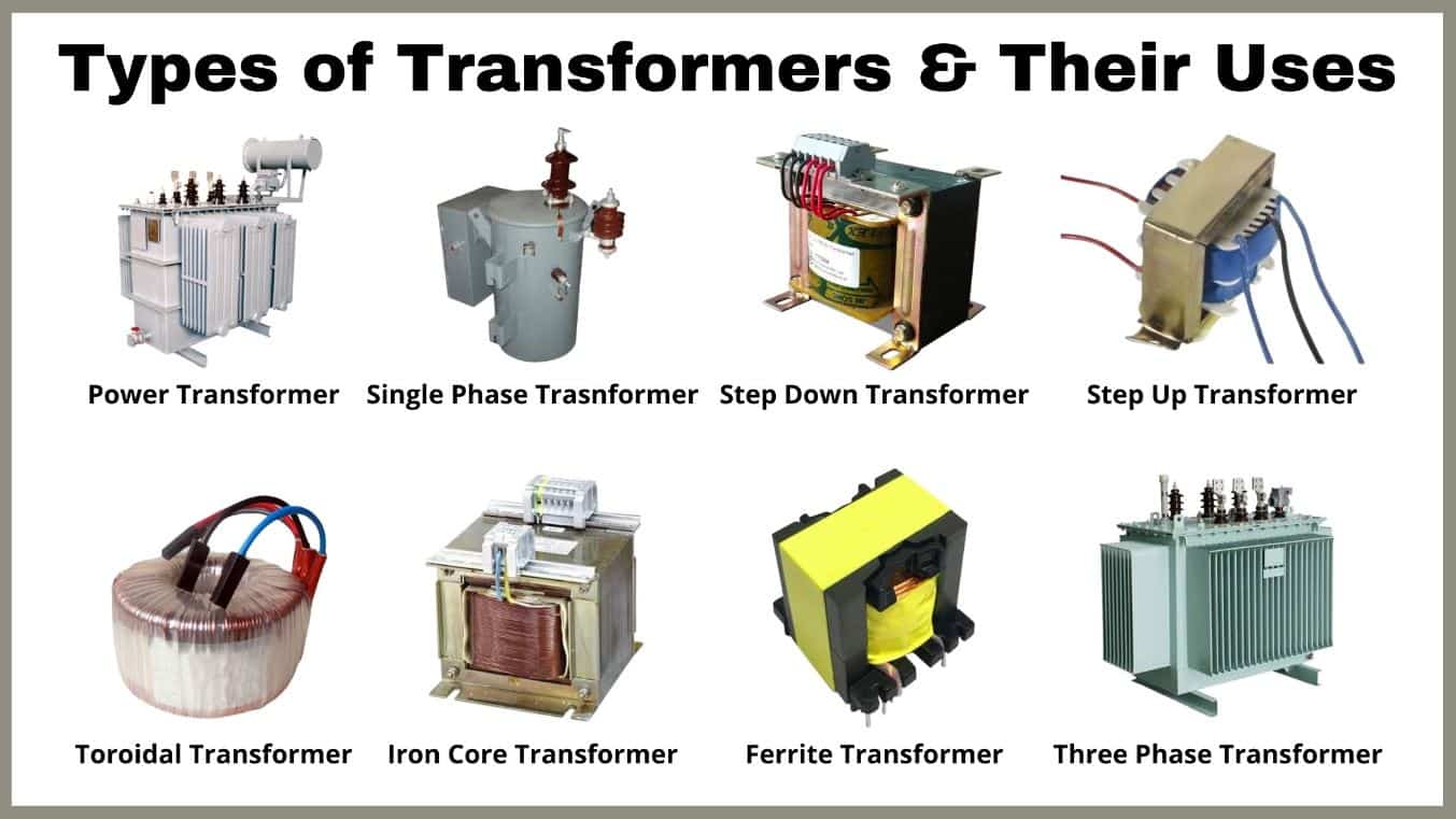
Similar to an electrical device, the efficiency of transformer is also introduced as the same ratio of output energy to the input energy (efficiency = output/input). Electrical machines like transformers are greatly efficient instruments. We know that various types of transformers exist in the market according to the application where the full power efficiency of these transformers differs from 95% to 98.5%. Once a transformer is typically efficient, then the output, as well as the input, has almost the same value. Therefore, it is not common to calculate the efficiency of the transformer by employing output/input. So, this post explains a complete overview of the efficiency of transformer.
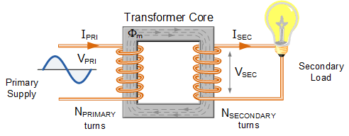
The efficiency of the transformer can be expressed as the intensity or the value of power waste through a transformer. Thus, the ratio of the secondary section’s power output to the primary section’s input can be obtained. The efficiency can be presented as the following:
Efficiency (η) = (Power Output/Power Input)
In general, efficiency can be expressed with ‘η’. The above equation is practical for a perfect transformer wherever there will be no transformer wastes as well as the full energy within the input gets moved to the output.
As a result, if transformer wastes are considered and if the efficiency of transformer is analyzed across the practical states, the next equation is mainly used.
Efficiency = ((Power O/P) / (Power O/P + Copper Losses + Core Losses)) × 100%
Or else it can be expressed as
Efficiency = (Power i/p – Losses) / Power i/p × 100 = 1− (Losses/i/p Power) × 100
So, all the input, o/p, and wastes are typically expressed in terms of power (Watts).
Power of a Transformer
Whenever an ideal device is considered with no wastes, then the power of the transformer will be stable since the voltage V has multiplied across the stable current I.
So, the power across the primary winding is identical to the power through the secondary section. If the voltage of the device increases, then the current will be reduced. Otherwise, if the voltage is reduced, then the current will be increased so that the power can be kept constant. Thus, the primary power is the same as the secondary power.
{P}_{primary}={P}_{secondary}
{V}_{P}{I}_{P}Cos({\phi }_{P})={V}_{S}{I}_{S}Cos({\phi }_{S})
Where ∅s and ∅P are secondary as well as primary phase angles.
Introduction of Efficiency of Transformer
Transformers create the most important connection between the load and supply systems. The efficiency of transformer directly influences its operation and aging. The transformer’s efficiency is generally in the range of 95 – 99 %. The efficiency can be as high as 99.7% for great power transformers with very low wastes. The output and input measurements of a transformer are not implemented under loaded conditions as the wattmeter sensing inevitably suffers errors of 1 – 2%.
Therefore, for the purpose of efficiency measuring, SC (Short Circuit) and OC (Open Circuit) tests are applied to measure rated core and winding wastes in the transformer. The core wastes are based on the transformer rated voltage, and the copper wastes are based on the currents across the transformer primary and secondary sides.
Hence, the efficiency of transformer is of prime importance to perform under fixed voltage and frequency conditions. The increase in the temperature of the transformer based on the heat produced affects the life of device oil features and determines the form of the cooling method adopted. The temperature rise restricts the level of the equipment. The efficiency of transformer is simply given as:
\eta =\frac{{P}_{O}}{{P}_{O}+Loss}\times 100
The output power is the product of the power factor of the load and the fraction of the rated loading (volt-ampere), and the wastes are the sum of the iron loss, the copper wastes in the windings, dielectric waste, and stray load waste.
The iron wastes contain the eddy current and the hysteresis wastes in the device. These wastes are based on the flux density inside the instrument. Mathematically, they can be calculated by the equations below:
- Hysteresis Loss:
{P}_{h}={K}_{h}f{B}_{max}^{n}
- Eddy Current Loss:
{P}_{e}={K}_{e}{f}^{2}{B}_{max}^{n}{t}^{2}
Where kh and ke are constants, Bmax is the maximum of the magnetic field density, f is the main frequency, and t is the thickness of the center. The power ‘n’ in the hysteresis equation is introduced as Steinmetz coefficient whose value can be nearly 2. So, the total iron or core wastes (Pi) can be calculated as the sum of the Hysteresis and Eddy current wastes.
The dielectric wastes take place through the transformer oil, which for low voltage applications, can be neglected.
The leakage flux connects to the metal frame, tank, etc. to create eddy currents and are existence all around the device hence introduced as stray loss, and it is based on the load current and so called ‘stray load waste.’ It can be expressed by resistance in series arrangement to the leakage reactance.
Efficiency Calculation of the Transformer
The equivalent circuit of the device referred to the primary section is presented below. Here Rc is used for core wastes. By employing Short Circuit (SC) test, we can find the identical resistance accounting for copper wastes as
{R}_{e}={R}_{1}+{R}^{'}_{2}
where
{R}^{'}_{2}={a}^{2}{R}_{2}
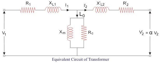
Let us purpose x as the percentage of full or rated load ‘S’ (VA), Pcufl(watts) as the complete load copper waste, and cos(θ) as the power coefficient of the load. We can also define Pi (watts) as the core waste. As copper and iron wastes are the main losses in the transformer hence only these two forms of losses are considered while measuring efficiency. Then the efficiency of transformer can be formulated as:
\eta =\frac{xsCos\theta }{xsCos\theta+{x}^{2}{P}_{cufl}+{P}_{i}}
Where x2Pcufl is the copper loss (Pcu) at any loading x percent of a complete load.
The maximum efficiency (ηmax) can be achieved when the variable wastes are identical to the constant losses. Because the copper waste is load dependent, hence it is a variable quantity. And the core waste is taken to be the fixed quantity. Therefore, the condition for maximum efficiency is:
x=\sqrt{\frac{P_{i}}{P_{cufl}}}
Now we can obtain the maximum efficiency as:
{\eta }_{max}=\frac{xsCos\theta }{xsCos\theta +2{P}_{i}}
This can demonstrate that we can achieve maximum efficiency at full load by appropriate choice of variable and constant wastes although it is problematic to obtain the maximum efficiency as copper wastes are much bigger than the fixed core losses.
The variation of efficiency with loading can be demonstrated by the figure below:
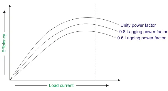
We can see from the diagram that the maximum efficiency happens at the unity power coefficient. The maximum efficiency happens at the equal loading irrespective of the load power factor.
Determination of Efficiency of Transformer
In general, the efficiency of a standard transformer is significantly high and varies from 96% to 99%. So, the efficiency of transformer cannot be determined through high precision by measuring output and input directly. The main dissimilarity between the readings of output and input and output of machines is very small that an instrument error will result in an error of the 15 % ranges within the transformer wastes.
In addition, it is not convenient to contain the necessary loading instruments of the exact ratings of power factor (PF) and voltage to load the transformer. There is also a high value of power loss and no information can be obtained from a test regarding the number of transformer wastes like iron and copper.
The transformer wastes can be specified with the accurate method to measure losses from open-circuit and short circuit tests, so that the efficiency can be identified.
From an open circuit method, iron waste like P1 = P0 or Wo can be obtained. From the short circuit method, the copper waste on full loads such as Pc = Ps or Wc can be achieved.
So, the efficiency of transformer can be determined as
{\eta }=\frac{V_{2}I_{2}Cos\Phi }{V_{2}I_{2}Cos\Phi +{P}_{i}+x^{2}P_{C}}
In the above formula, the result of instrument readings can be limited to wastes easily so that the whole efficiency obtained from this is very precise compared with the efficiency gained through direct loading.
Maximum Efficiency Condition of a Transformer
We purpose copper loss as I12.R1, and Iron loss as Wi. So, the efficiency can be defined as:
{efficiency}=1-\frac{losses}{Input}=1-\frac{I_{1}^{2}R_{1}+W_{i}}{V_{1}I_{1}Cos\Phi_{1}}
{\eta}=1-\frac{I_{1}R_{1}}{V_{1}I_{1}Cos\Phi_{1}}-\frac{W_{i}}{V_{1}I_{1}Cos\Phi_{1}}
If we differentiate the above equation with respect to I1, so we have:
\frac{d\eta}{dI_{1}}=0-\frac{R_{1}}{V_{1}Cos\Phi_{1}}+\frac{W_{i}}{V_{1}I_{1}^{2}Cos\Phi_{1}}
The efficiency will be large at dη/dI1 = 0. Thus, the efficiency of transformer will be high at
\frac{R_{1}}{V_{1}Cos\Phi_{1}}=\frac{W_{i}}{V_{1}I_{1}^{2}Cos\Phi_{1}}
I_{1}^{2}R_{1}=W_{i}
As a result, the efficiency of transformer will be great once iron and copper losses are equivalent. Visit here to explore more about these losses and the efficiency of transformer completely.
Losses in Transformer
In any electrical device, ‘loss’ can be introduced as the difference between the output power and input power. An electrical transformer is a static instrument, hence mechanical wastes (like friction or windage losses) are absent in it. A transformer only includes electrical wastes (copper losses and iron losses). Transformer wastes are similar to losses in a DC device, except that transformers do not consist of mechanical losses. Main losses in a transformer are explained below:
Core Losses or Iron Losses
Eddy current and hysteresis losses are based on the magnetic features of the material applied for the production of the core. Thus, these wastes are also introduced as core losses or iron losses.
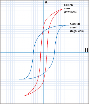
Hysteresis Loss in Transformer
Hysteresis loss is based on reversal of magnetization in the device core. This waste is based on the frequency of magnetic reversals, the volume and grade of the iron, and the amount of flux density. It can be obtained by Steinmetz formula:
W_{h}=\eta B_{max}1.6fV(watts)
where η is Steinmetz hysteresis constant and V is the volume of the core in m3.
Eddy Current Loss in Transformer
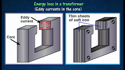
In the transformer, A.C is provided to the primary side which determines the alternating magnetizing flux. Once this flux links with the secondary side, it generates induced EMF in it. But some components of this flux also get linked with other conducting sections like iron body or steel core or the transformer, which will produce induced EMF in those parts, causing small flowing current in them. This current is introduced as eddy current. Because of these eddy currents, some power will be dissipated in the form of heat.
Copper Loss in Transformer
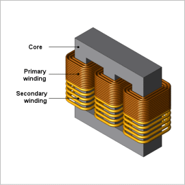
Copper loss is because of ohmic resistance of the device windings. Copper waste for the primary section is I12R1 and for the secondary side is I22R2; where I1 and I2 are currents in primary and secondary sections respectively, R1 and R2 are the resistances of primary and secondary sides. It is obvious that Cu waste is related to the square of the current, and current is based on the load. Therefore, the copper loss in the device changes with the load.
All Day Efficiency of Transformer
As we have seen above, commercial or ordinary efficiency of transformers can be obtained from the ratio of the output to the input in watts.
But in some forms of devices, their operation cannot be measured by this efficiency. For instance, distribution transformers have their primaries powered all over time. But their secondary sections provide little load all no-load most of the time during their operating cycle (as residential utilization of electricity is observed mainly during evening till midnight).
That is, when the secondary side of the transformer does not provide any load (or providing only a little load), only core wastes of the device are considerable and copper wastes are absent (or very little). Copper wastes are considerable only when transformers are powered. Therefore, for such devices, copper losses are roughly less important. The operation of such transformers is compared to the foundation of energy used in one day. The all-day efficiency of a device is often less than the ordinary efficiency of it.
It is an energy-based efficiency evaluated for distribution applications. Unlike a power transformer that is switched off or in depending on the load handled by it, a distribution device loading continuously varies for 24 hours a day. As core wastes are independent of the load, the all-day efficiency is based on the copper wastes. We introduce it as the level of output power delivered to input power for a 24-hour cycle. High power efficiencies are obtained by restricting core flux densities to lower amounts (as the core wastes are dependent on flux density) by employing a relatively greater cross-section or larger iron/copper weight ratio.
How to Improve the Efficiency of Transformer?
There are several methods to improve the efficiency of transformer including insulation, loop area, flux coupling, and coils resistance.
- Loop area
This area should be considered to determine the efficiency of transformer.
- Insulation
The insulation across the core sheets should be ideal to prevent eddy currents.
- Primary and Secondary Coil’s Resistance
The substance of the primary and secondary sides should be stable so that their electrical resistance is considerably little.
- Flux Coupling
Both sections of the transformer should be wound in such a manner that flux coupling across the coils is utmost as power transfer from one side to another will occur during flux linkages.
Therefore, this is all about an overview of the efficiency of transformer. Transformers are electrical instruments with high efficiency. So, most of the transformer’s efficiency will vary from 95% to 98.5%.
What Makes Transformers so Efficient?
A transformer decreases the voltage of the electricity provided by your utility so that it can be used by electric equipment in your facility. Your company uses all its electricity through transformers, so even a small improvement in efficiency could result in substantial savings.
Download PDF for Efficiency of Transformer
If you would like to read this article whenever you like, you can download it as a PDF file.
Read More In Linquip
- Power System Services
- Power System Maintenance Services
- Power System Installation Services
- Power Systems Services in Texas
- Power System Maintenance Services in Texas
- Power System Installation Services in Texas
- EMF Equation of Transformer– Turns Voltage Transformation Ratio of Transformer
- What is the Equivalent Circuit of Transformer?
- Current Transformer Types and Applications
- What is Electrical Transformer?
- What is Auto Transformer? Advantages & Application
- Working Principle of Transformer: Discover the Mechanism Involved in the Operation
- Difference between Power Transformer and Distribution Transformer
- What is the Efficiency of Transformer?
- What is Step-Down Transformer and Its Application?
- Difference Between Step Up and Step Down Transformer
- What is Step Up Transformer?
- What is a Distribution Transformer?
- What is a Single Phase Transformer?
- What is Power Transformer?
- What is the Current Transformer?
- What is Potential Transformer?
- Construction of Transformer: Uncover The Parts and Construction
- What is the Equivalent Circuit of Transformer?
- EMF Equation of Transformer- Turns Voltage Transformation Ratio of Transformer
- Difference Between Step-Up and Step-Down Transformer: A Quick Guide
- Types of Transformer: An Article About How Transformers Differ in Construction and Design
- Top Transformers Manufacturers and Suppliers in the USA and Worldwide

