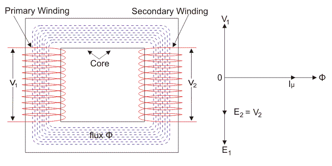
The magnitude value of the particular Voltage or the induced EMF in a transformer can be discovered by the EMF equation of transformer. When a supply of alternating current (AC) is operated on the basic winding of the transformer which is introduced as magnetized current, it generates the alternating type of flux in the center of a transformer. The generated alternating type of flux in the basic section of the transformer becomes related with the second part of the transformer by specific induction as it is naturally alternating flux, there should be a level of flux variation based on Faraday’s law of electromagnetic effect which presents that if a coil or conductor relates with any flux, there should be an induced electromotive force in it.
What is the Emf Equation of Transformer?
EMF Equation of transformer can be evaluated in a very simple method. One alternating electric supply is operated practically on the main winding in the electrical power transformer, and according to this, magnetizing flow within the basic winding which generating alternative flux in the base of the transformer. This flux influences both secondary and primary windings. There should be enough value of change in flux because this flux is alternating.

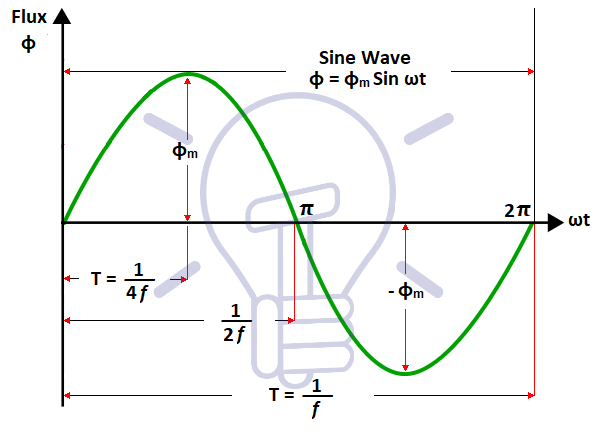
As the current supply operated on the base of the system is sinusoidal, the flux produced by it will also be in this form. So, the flux operation can be considered as a sine function. The derivative of that function will mathematically present a performance for the value of flux variation that is linked to time. This final function is like a cosine function because
\frac{dsin\theta }{dt}=cos\theta
So, if we extract the mathematic term for the RMS value of this cosine function and improve it with the turns number of the winding, we can easily derive the RMS expression of specific EMF and EMF equation of transformer.
As discussed before, the source of alternating current in a transformer is operated to the first winding. The current in the first winding which was introduced as the magnetizing current generates alternating flux based on this effect in the center of the transformer. This alternating flux can influence the second winding, and an EMF will be produced in the secondary winding according to this phenomenon. The magnitude of this particular EMF can be calculated by employing the following EMF equation of the transformer.
When a sinusoidal wave is operated on the basic winding of a transformer, alternating flux Φm is generated in the iron core of the device. This special flux affects both secondary and primary windings and the operation of them is like a sine function. Visit here to see the fundamental operation of a transformer clearly.

The state of flux modification based on time can be calculated mathematically. The main principle of the EMF Equation of transformer is presented below. Let
Φm: the maximum amount of flux is presented in Weber unit
f: the source frequency based on Hz
N1: turns number in the first winding
N2: turns number in the second winding
Φ: flux per turn based on Weber unit

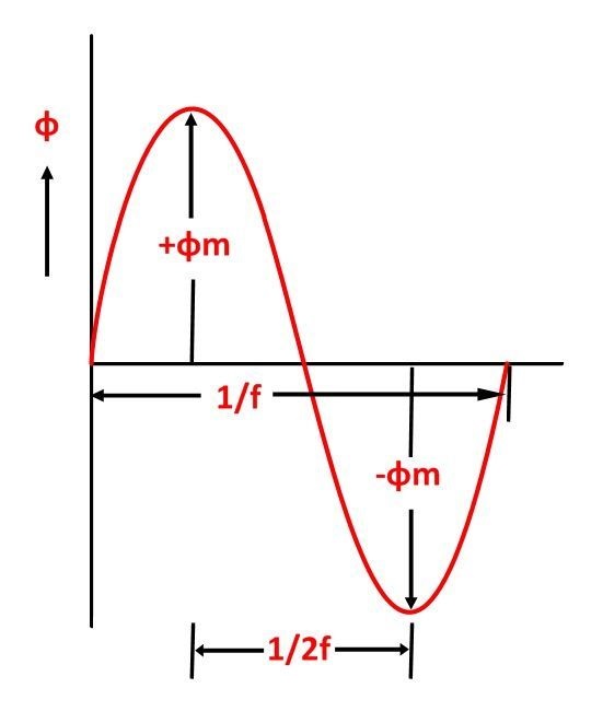
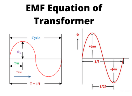
As presented in the last figure, the flux varies from + Φm to – Φm in 1/2f seconds or half a period. According to Faraday’s Law, consider E1 as the emf produced in the basic winding
{E}_{1}= -\frac{d\psi }{dt}
Where
\psi ={N}_{1}\Phi
Therefore,
{E}_{1}={-N}_{1}\frac{d\Phi }{dt}
AS ϕ is generated based on the AC supply
\Phi={\Phi }_{m}. sin\omega t
{E}_{1}={-N}_{1}\frac{d}{dt}({\Phi }_{m}sin\omega t)
{E}_{1}={-N}_{1}\omega {\Phi }_{m}cos\omega t
{E}_{1}={N}_{1}\omega {\Phi }_{m}(sin\omega t-\frac{\pi }{2})
So, the produced emf lags the flux by 90o. Therefore, the maximum rate of emf can be evaluated as:
{E}_{1max}={N}_{1}\omega {\Phi }_{m}
But
\omega =2\pi f
so;
{E}_{1max}=2\pi f {N}_{1}{\Phi }_{m}
RMS value or Root Mean Square can be calculated as:
{E}_{1}=\frac{{E}_{1max}}{\sqrt{2}}
By using the value of E1max in the last equation, we can get
{E}_{1}=\sqrt{2}\pi f{N}_{1}{\Phi }_{m}
If we put the value of π = 3.14 in the previous equation, we can obtain the value of E1 as
{E}_{1}=4.44 f{N}_{1}{\Phi }_{m}
Similarly;
{E}_{2}=\sqrt{2}\pi f{N}_{2}{\Phi }_{m}
Or
{E}_{2}=4.44 f{N}_{2}{\Phi }_{m}
Now, based on the equation of E1 and E2, we can obtain:
\frac{{E}_{2}}{{E}_{1}}=\frac{{N}_{2}}{{N}_{1}}=K
The above formula is introduced the turn coefficient where K is called the transformation ratio.
Voltage Ratio of Transformer
The voltage ratio of transformer is the other term for this above-stated rate when it is presented as the coefficient of the secondary and primary voltages of the transformer.
Turns Ratio of Transformer
As the voltage in secondary and basic windings of the transformer is instantly related to the number of turns in the determined winding, so the transformation ratio of the instrument is occasionally presented in the ratio of turns and introduced as the turns ratio of the transformer. The “K” coefficient is called the ratio of voltage transformation.
If N2 > N1, or K > 1, so the transformer is introduced as the step-up type of transformer.
If N2 < N1, or K < 1, so the transformer is known as the step-down type of transformer.
Where,
N1 is the basic turns number of the coil in the instrument, and N2 is the secondary turns number.
The previous equations of E1 and E2 can also be presented as shown below using the next formula:
{\Phi }_{m}={B}_{m} \times {A}_{i}
where the Ai coefficient is the iron section and Bm is the maximum amount of flux density.
{E}_{1}=4.44{N}_{1}f{B}_{m}{A}_{i}
And
{E}_{2}=4.44{N}_{2}f{B}_{m}{A}_{i}
Especially, for a sinusoidal function, Form factor can be defined as:
\frac{R.M.S Value}{Average Value}=FormFactor=1.11
Here, the calculated form factor is 1.11.
Buy Equipment or Ask for a Service
By using Linquip RFQ Service, you can expect to receive quotations from various suppliers across multiple industries and regions.
Click Here to Request a Quotation From Suppliers and Service Providers
Read More On Linquip
- Efficiency of Transformer
- Types of Transformer: An Article About How Transformers Differ in Construction and Design
- All You Need to Know about Final Value Theorem
- What is the Equivalent Circuit of Transformer?
- Difference Between Step-Up and Step-Down Transformer: A Quick Guide
- Transformer Efficiency: Essential Things You Should Know
- Mastering the Art of Calculating Transformation Efficiency: A Comprehensive Guide by Linquip
- Mastering Nuclear Equation Calculations with Linquip’s Expert Guidance
- Ultimate Guide to Ceiling Fan Size Calculator by Linquip
- In-Depth Guide to Inverter Battery Calculators on the Linquip Platform


