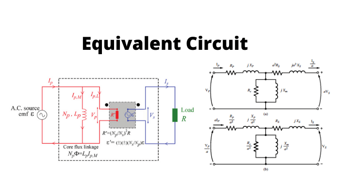
Equivalent Circuit of Transformer is an electrical circuit explanation of equations representing the behavior of that Transformer. In fact, an equivalent circuit of any electric instrument is important for the analysis of its performance and to discover any scope of further modification of modeling. The equivalent circuit of transformer includes a setup of inductance, resistance, voltage, capacitance, etc. These circuits can then be analyzed and explored by applying the principles of the diagram’s theory.
A graphical depiction of a transformer circuit in which the resistance and leakage reactance are considered to be external to the winding is called an equivalent circuit of a transformer. The main or secondary side of a transformer refers to the identical equivalent circuit. Transformers are available from a variety of Suppliers and Companies, as well as various manufacturers and distributors, and there are several Transformers for Sale on Linquip.
There is a complete list of transformer equivalent circuit services on the Linquip website that covers all factory operations. Linquip providers can assist you with this. Please contact Linquip’s Transformer Experts to learn more about how to connect with a diverse group of service providers who consistently deliver high-quality items.
⇒ View a List of Transformers for Sale and Their Suppliers ⇐
What is the Equivalent Circuit of Transformer?
The equivalent circuit or diagram of any system can be relatively useful in the pre-specification of the performance of the instrument under the different situations of various operations. It can easily represent the circuit behavior by a particular equation describing the situation of the system completely.
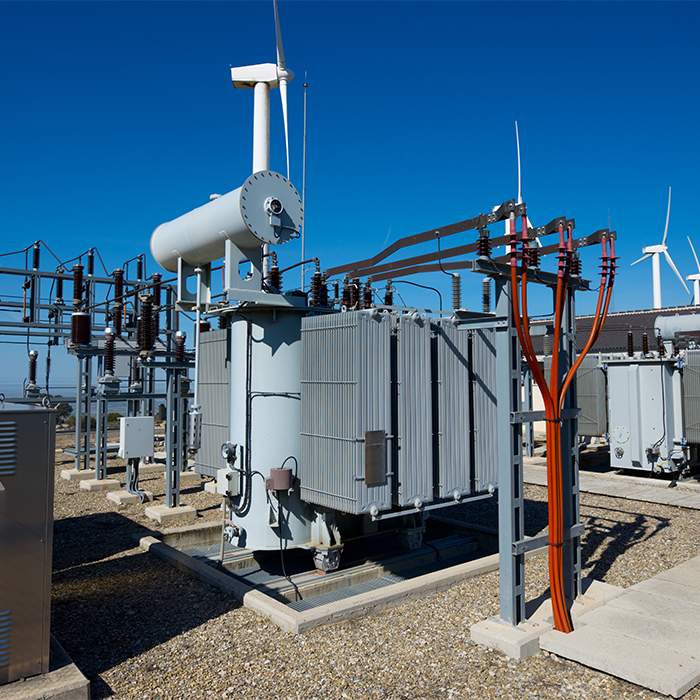
For instance, equivalent impedance of the system is vital to be evaluated since the transformer is the electrical power instrument for considering several features of the electrical power device which may be needed to evaluate the whole internal impedance of the transformer in an electrical power system, exploring from primary or secondary side based on the requirement.
This estimation actually needs the equivalent circuit of transformer based on the basic side of the equivalent circuit of transformer and secondary side respectively. Relative impedance is also a very important characteristic of the transformer. Visit here to see the importance of this calculation in the design of any circuit.
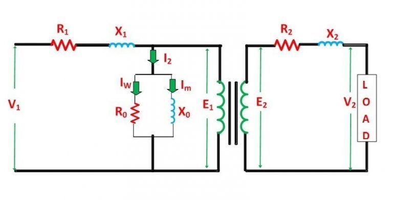
The simplified equivalent circuit of a transformer is presented by considering all the properties of the transformer either on the primary or secondary side. The main equivalent circuit of the transformer is shown below in the diagram:
A high percentage of consideration is to be given to this feature for the installation of a transformer in an existing system of electrical power. The relative impedance of various power transformers must be completely matched based on the parallel configuration of power systems. The relative impedance can be extracted from the equivalent value of the transformer’s impedance so, it can be noticed that the equivalent circuit of transformer is also important during the estimation of the relative impedance.
We can define the equivalent circuit of transformer based on the transformation ratio as:
K=\frac{{E}_{2}}{{E}_{1}}
Where E1 is the induced emf equal to the main employed voltage (V1) with a little voltage reduction. This voltage influences the system to produce the I0 current or no-load current in the first winding of the transformer. The amount of no-load current is too little, and thus, it may be neglected in calculations.
We should primarily establish general rules in the system for driving the equivalent circuit of transformer, then, we can change it for preparing to define the rules based on the primary side. For this purpose, first, we require to present a full vector diagram of the transformer which is presented in the figure below.
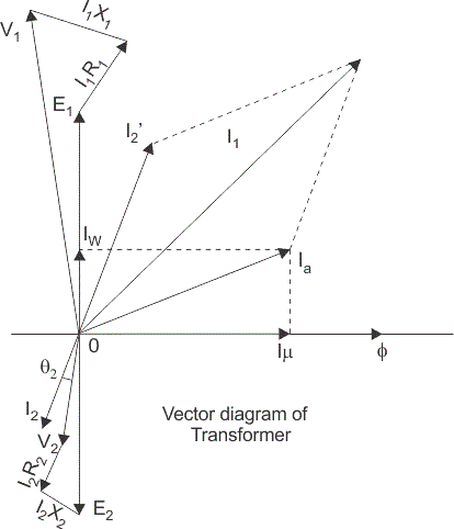
As a result, I1 = I’1. The no-load current is further separated into two sections introduced as the magnetized current (Im) and operating current (Iw).
These two sections of no-load current are based on the current derived from a non-inductive resistance R0 and net reactance X0 including voltage E1 or (V1: basic voltage reduction).
The second current I2 can also be calculated by the next equation:
{I}_{2}=\frac{{I}_{1}^{'}}{K}=\frac{{I}_{1}-{I}_{0}}{K}
The connection voltage V2 within the load is the same as the particular emf E2 in the next winding with a little voltage reduction in the second winding.
Equivalent Circuit of Transformer when all the quantities are referred to Primary side
In this method, to derive the equivalent circuit of transformer, all the features are to be considered as the primary section as presented in the figure below:
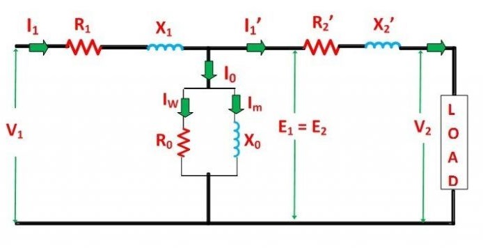
The following quantities are the values of resistance and reactance that can be calculated by the next equations. Secondary resistance based on the primary side is obtained as:
{R}_{2}^{'}=\frac{{R}_{2}}{{K}^{2}}
The equivalent resistance according to the primary consideration is obtained as:
{R}_{ep}={R}_{1}+{R}_{2}^{'}
The second reactance based on the primary side is presented as:
{X}_{2}^{'}=\frac{{X}_{2}}{{K}^{2}}
The equivalent reactance depends upon the primary side is obtained as:
{X}_{ep}={X}_{1}+{X}_{2}^{'}
Approximate Equivalent Circuit of Transformer
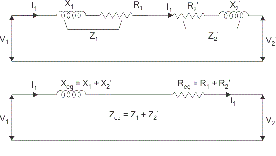
Due to the small value of I0 in comparison with I1, it is less than 4 percent of the total load of the primary current and modifies the voltage reduction negligibly. As a result, it is a perfect approximation to reduce the excitation effect of the circuit in the approximate equivalent circuit of transformer method. The resistance and reactance of winding are arranged in a series configuration which can now be introduced as the equivalent reactance and resistance of transformer, based on any particular side. But in this method, it is the primary side or side 1 that determines the features of the circuit based on the next equation:
{V}_{2}^{'}=K{V}_{2}
Equivalent Circuit of Transformer when all the quantities are referred to Secondary side
The equivalent circuit of transformer or the basic diagram is presented below when all the features are designed based on the secondary side.
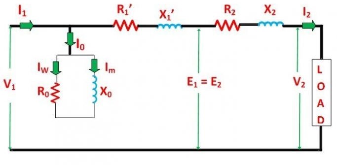
The following properties are the values for resistance and reactance which can be obtained below. Basic resistance based on the secondary side is formulated as
{R}_{1}^{'}=K^{2}{R}_{1}
The equivalent value of resistance according to the secondary term is obtained as
{R}_{es}={R}_{2}+{R}_{1}^{'}
The primary value of reactance based on the secondary side is presented as
{X}_{1}^{'}=K^{2}{X}_{1}
And the equivalent value of reactance is obtained as
{X}_{es}={X}_{2}+{X}_{1}^{'}
Because the no-load current or I0 is commonly 2 to 4 percent of the full load value of rated current, the parallel configuration includes the R0 resistance and X0 reactance can be removed from the circuit without introducing any particular error in the performance of the transformer when the load is applied.
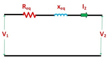
We can also apply further simplification in the equivalent circuit of transformer by removing the parallel terms in the circuit including R0 and X0. This simplified diagram of the system is presented below:
This is all considerable issues about the equivalent circuit of the Transformer.
Download Equivalent Circuit of Transformer PDF
Buy Equipment or Ask for a Service
By using Linquip RFQ Service, you can expect to receive quotations from various suppliers across multiple industries and regions.
Click Here to Request a Quotation From Suppliers and Service Providers
Read More on Linquip
- Types of Transformer: An Article About How Transformers Differ in Construction and Design
- What Is the Advantage of AC Power Transmission?
- EMF Equation of Transformer- Turns Voltage Transformation Ratio of Transformer
- Transformer Efficiency: Essential Things You Should Know
- Why DC Current Is Not Used In Homes
- HVDC vs HVAC Transmission Systems- Difference between them
- Difference Between Step-Up and Step-Down Transformer: A Quick Guide
- What are the Advantages of AC over DC?
- What is the benefits of AC in Long-distance Transmission?
- Efficiency of Transformer
- What is Auto Transformer? Advantages & Application
- What is Electrical Transformer?
- Working Principle of Transformer: Discover the Mechanism Involved in the Operation
- Difference between Power Transformer and Distribution Transformer
- What is the Efficiency of Transformer?
- What is Step-Down Transformer and Its Application?
- What is Step Up Transformer?
- What is Power Transformer?
- What is Electrical Identification? (2022 Ultimate Guide)

