This is a detailed guide to resistor color code. It is easy to read resistor color codes after learning what each band means and how it is calculated. In some cases, even the temperature coefficient is indicated by each band.
Linquip offers a wide range of information about resistors so that you have a complete understanding of them. More details about Linquip’s solutions for your situation can be found on our “Electrical” page. Now is the time to learn about the color codes of resistors so that you can make your job easier.
If you are not familiar with resistor color codes, it can be challenging to choose the right one. With Linquip, you’ll be able to find a wide range of Electrical Products. With the Linquip Platform, you will be able to receive free quotes from a number of Electrical Suppliers and Companies.
It is possible to purchase resistors in a wide variety of values, shapes, and physical sizes. There is a pattern of colored bands almost universally found on all leaded resistors up to one watt in order to indicate resistance, tolerance, and in some cases the temperature coefficient of the resistor. On a resistor, you will usually find three to six colored bands, but four is the most common. The first few bands denote digits in the resistance value. You will then see a multiplier band signifying the right or left movement of the decimal point. Lastly, there are bands representing tolerance and temperature coefficients.
How can we read the color code on a resistor? Why do some resistor color codes consist of four bands and others of five bands? What about three and six-color bands? In this article, we answer all of these questions and provide you with the tools you need to quickly determine the correct resistor for all of your projects.
Basics of Resistors Color Code
In order to quickly and easily identify the ohmic value of a resistor, an international and universal color code scheme was established in the past. It is composed of an array of individual colored rings or bands corresponding to each digit of the resistor’s value.
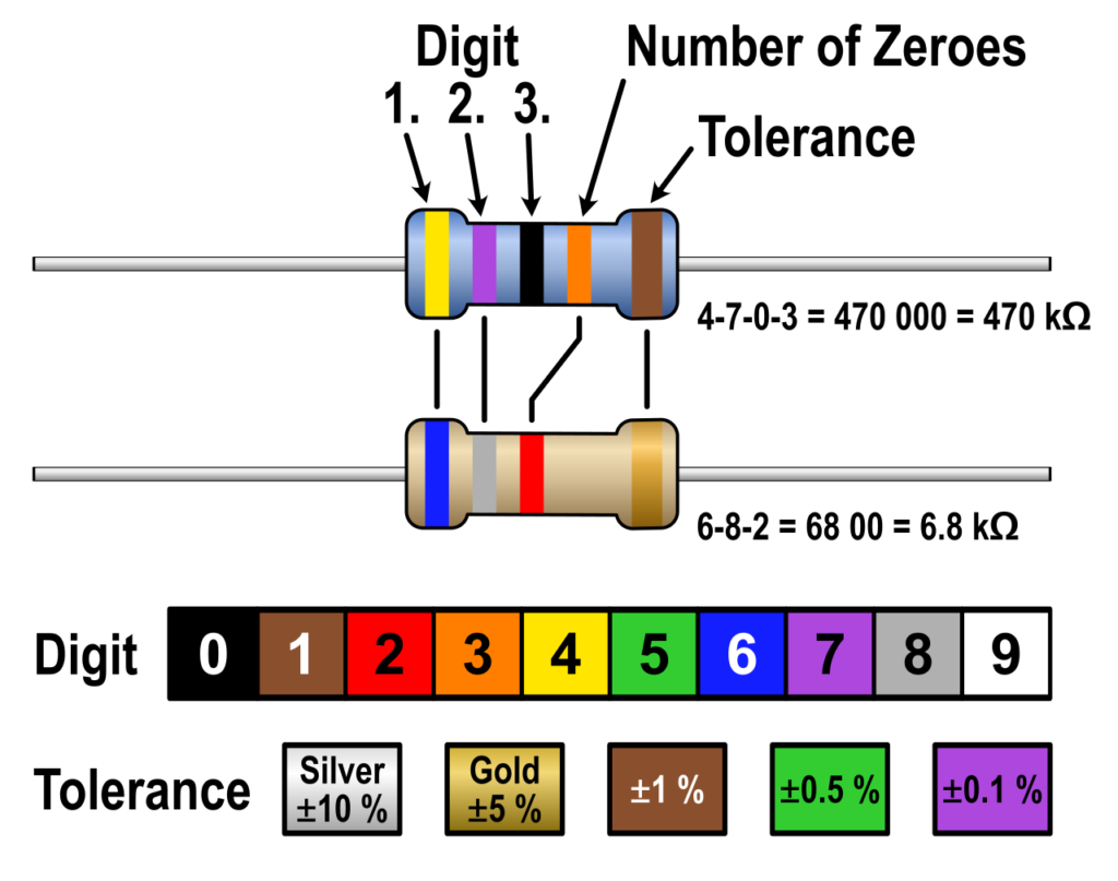
Each band of the resistor color code marking is read one by one, starting from the left side, with the tolerance band closest to the right side. The color of the first band is based on the number in the digit column of the following chart, which indicates the resistance value’s first digit.
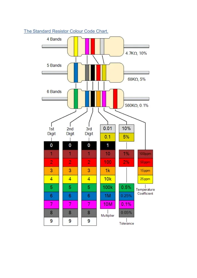
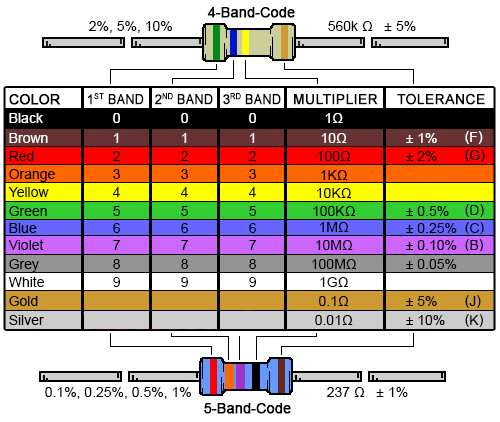
Again, matching the color of the second band to its corresponding digit of the color chart gives the second digit of the resistance value. This can be repeated for the remaining bands. Using the illustration below, read the resistor color code from left to right:
Three- or Four-Band Resistors
A resistance value in ohms is always represented by the first two bands. In three-band or four-band resistors, the third band specifies the multiplier. By shifting your decimal place around, this multiplier will transform your value from megaohms to milliohms, or any other value in between. The fourth color band represents tolerance. When this band is absent, the default tolerance on a three-band resistor is 20%.
Five- or Six-Band Resistors
To indicate a third significant digit, high-precision resistors have an additional color band. In resistors with five or six color bands, the third band joins bands one and two as an additional digit. Other than that, every other color band moves to the right, with the fourth color band being the multiplier and the fifth color band indicating tolerance.
In general, a six-band resistor is a five-band resistor with another ring marking the reliability or temperature coefficient (ppm/K). As an example, for brown, commonly seen in the sixth band, every 10°C change in temperature changes the resistance value by 0.1%.
Calculating Resistor Color Code Values
To get the correct resistor value, we need to understand how to apply the Resistor Color Code system. Typically, the left-hand colored band is closest to a connecting lead and the color-coded bands can be read as follows in order of left-to-right:
Digit, Digit, Multiplier = Color Color x 10^color (Ohms (Ω))
An example of colored markings on a resistor is as follows;
Yellow Violet Red = 4 7 2 = 4 7 x 10^2 = 4700Ω
A resistor’s percentage tolerance is determined by its fourth and fifth bands. Tolerance is the difference between a resistor’s nominal value and its variation from that value as a result of the manufacturing process, expressed as a percentage.
In general, film resistors have tolerances of 1% to 10%, whereas carbon resistors can have tolerances as high as 20%. Precision resistors are those with tolerances less than 2%, and they are more expensive than resistors with higher tolerances.
There are most often tolerances of 1% or 2% on five-band resistors, whereas most tolerances are 5%, 10%, or 20% on four-band resistors. To indicate the tolerance rating of a resistor, the color code is:
Brown = 1%, Red = 2%, Gold = 5%, Silver = 10 %
If there is no fourth tolerance band on a resistor, then a default tolerance of 20% would apply.
Reading Resistor Color Codes
Due to their lack of polarity, resistors can be installed in any orientation. Color code values on resistors can be determined by understanding the colored bands.
Four-band hobby resistors typically have three colors in a group. The first, second, and multiplier significant figures can be found here. There is a final band, which is the tolerance of the resistor, a margin for error. Hobbyists generally accept a tolerance of 5% (Gold).
Only sensitive circuits, such as audio and video projects, require extra precision. There is only one band printed on the “shoulder” of the resistor, which is the tolerance band. Identify the resistor’s orientation by looking for this band.
For an example of how to read resistor color codes, let’s look at a 220 Ohm resistor commonly used with LED lights.
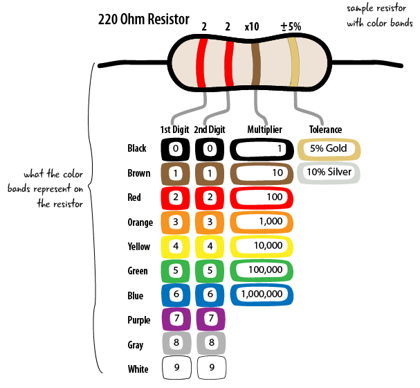
- Red is the first color, and its value is 2, as we can see from the decoder.
- Similarly, the second color is red, so we get 22.
- There is a brown multiplier, which decodes to 10. Multiplying 22 by 10 gives us 220.
- Tolerance, the final band, is gold. There is a margin of error of 5% for gold, in other words, we can accept a resistance with a margin of error of 5%.
Additionally, there are five band resistors with a third significant figure for makers who require greater precision. In circuits sensitive to resistance, such as scientific and engineering instruments, the extra figure provides clarity.
Below is a resistor color code for a 220 Ohm five-band resistor.
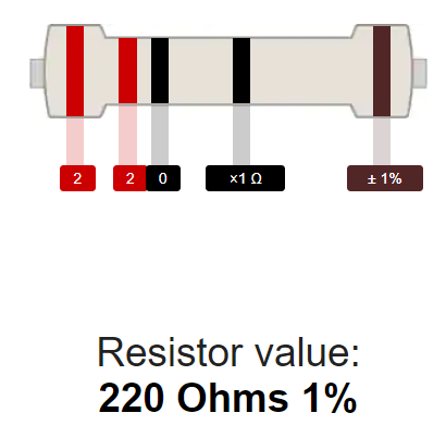
- According to the decoder, red has a value of 2 as the first significant figure.
- There is a second significant figure that is also red, so we have 22.
- Three significant figures correspond to zero, as indicated by black. Now we have 220.
- The multiplier is black, which decodes to 1. Multiplying 220 by 1 gives us 220.
- The last band is black, which represents tolerance. With black being 1%, we can accept a resistance that is within a 1% range of error.
The British Standard Code (BS 1852)
It is generally not necessary to use resistor color code systems on larger power resistors since the resistance value, tolerance, and even the power rating (wattage) are printed on the resistor body itself. An easier system was developed for writing and printing the resistance values of the individual resistances in part due to the ease with which a decimal point or comma can be misread on dirty or discolored components.
As per BS 1852 Standards, as well as its successor, BS EN 60062, this system replaces the decimal point position with a suffix of “K” for thousands and kilohms, “M” for millions and mega ohms, which are used to denote the multiplier value with “R” being used in cases where the multiplier equals or is less than one, and any number following these letters is equivalent to a decimal.
BS 1852 Letter Coding for Resistors
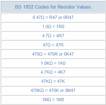
Depending on the manufacturer, there is sometimes an additional letter following the resistance value that indicates the resistors tolerance amount, such as 4k7 J. These suffix letters are given as follows:
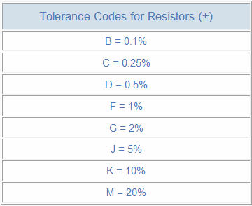
Resistor Colour Code for Tolerance, E-series, and Preferred Values
There are many types of resistors available in different sizes and resistance values, but in order to have a resistor for every resistance available, literally hundreds of thousands, if not millions of individual resistors are required. Preferred values are used instead when manufacturing resistors.
Resistor values are not sequentially specified but are listed within certain tolerances. Tolerance refers to the maximum difference between the actual and required values of a resistor, and it is generally expressed as a percentage. For instance, a 1kΩ ±20% tolerance resistor could have the following maximum and minimum resistive values:
Maximum Resistance Value= 1kΩ or 1000Ω + 20% = 1,200Ω
Minimum Resistance Value= 1kΩ or 1000Ω – 20% = 800Ω
As you can see from the example above, a 1kΩ ±20% tolerance resistor is capable of a maximum value of 1200Ω and a minimum value of 800Ω which results in a difference of 400Ω using the same resistor value.
A 20% tolerance on the same resistor is normally not a problem in most electrical or electronic circuits, however, when resistors with close tolerances are required for high-accuracy circuits such as filters, oscillators, amplifiers, and so on, the correct tolerance resistor must be used, as a 20% tolerance resistor does not meet 2% or even 1% tolerances.
The five-band and six-band resistor color codes are more common on high precision 1% and 2% film resistors, while four-band resistor color codes are more common on 5% and 10% general purpose types. Resistors come in a variety of tolerances, but E12 and E24 series are the most common.
Resistance values for the E12 series are based on a decade of 10 values, i.e. 10, 100, 1000, while for the E24 series twenty-four values per decade are used, and for the E96 series it is ninety-six values per decade. With the E192 series, you can now get very high precision with tolerances of just ± 0.1%, which results in 192 separate resistor values per decade.
FAQs
- Which end of the resistor should I read first?
- The color bands of many resistors are grouped closer together or toward one end. You should hold the resistor to your left with these bands grouped together. When reading resistors, always read them left to right.
- There is never a metallic band on the left side of a resistor. You have a 5% or 10% tolerance resistor if it has a gold or silver band at one end. This band should be on the right side of your resistor, and you should read it from left to right.
- A basic resistor ranges in value between 0.1 ohm and 10 megaohm. Taking this into account, remember that the third color of a four-band resistor will always be blue (106) or less, while the fourth color of a five-band resistor should be green (105) or less.
- What are the reasons for not using metallic colors in my high voltage resistor?
To prevent metal particles from being embedded in the exterior coating of high voltage resistors, gold and silver are replaced with yellow and gray.
- How does a zero-ohm resistor work?
In printed circuit boards, zero-ohm resistors are wire links that are easily recognizable by their single black band. As they are packaged like resistors, they can also be placed on circuit boards using the same automated equipment as resistors. Using this design, a jumper wire is not required to be installed separately.
- What is the best way to memorize the chart’s colors?
A number of mnemonics are available on the Internet for memorizing color code for resistors, but some are easier to remember than others. As another way to memorize the color chart, consider black as the absence of color, which is “0”; white, on the other hand, is the combination of all colors, which is “9”. For the numbers 2 through 7, you’ll find rainbow colors arranged in order, so your childhood ROY-G-BIV acronym applies, except for the color indigo. You just need to remember that brown lies in the middle of black and red as “1” and gray lies between violet and white as “8” and you’re done!
- What does the term “reliability” band mean?
Usually, military-specified resistors have an additional band on four-band resistors that is used to represent reliability or the failure rate expressed in percentage) per 1,000 hours of operation. Commercial electronics rarely use this.
Conclusion
The purpose of this article is to provide you with essential information about resistor color codes. With this knowledge in hand, get out there and impress all your friends now that you’ve learned the basics and tricks. Contact Linquip Electrical Experts if you have any questions about choosing the right resistor for your particular application. In addition, the Linquip platform also connects you with a variety of Electrical Service Providers if you need services related to your electrical equipment.
Download PDF for Guide to Resistor Color Code
You can download the PDF format of this post from the link provided here.
Buy Equipment or Ask for a Service
By using Linquip RFQ Service, you can expect to receive quotations from various suppliers across multiple industries and regions.
Click Here to Request a Quotation From Suppliers and Service Providers
Read More On Linquip
- What is Shunt Resistor? + Function & Applications
- What Are Resistors for LED Circuits? (Clear Guide)
- What is Braking Resistor? (A Practical Guide)
- All You Need to Know About Guide to Resistor Values
- Mastering Resistance Calculations: A Comprehensive Guide for Electrical Enthusiasts
- What is Pull-up and Pull-down Resistors? + Typical Application
- A Quick Guide to Resistor Sizes and Packages
- Types of Resistor: Classification, Application, and Finally Clarification
- Variable Resistor Symbol։ Everything You Need to Know
- Variable Resistor∶ Learn The Basics, Get The Most out of It!
- Everything You Need to Know About Variable Resistor Function

