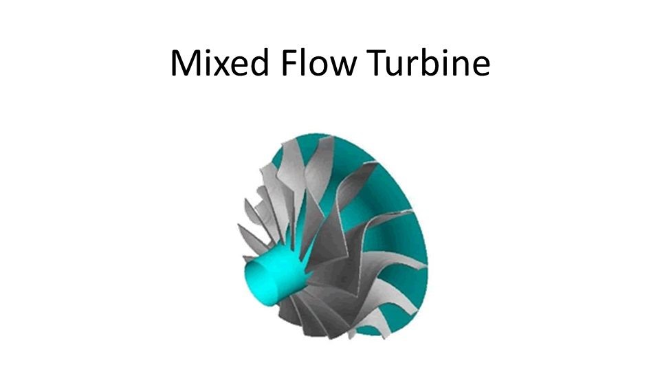
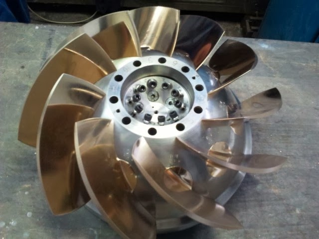
A mixed flow turbine can be seen as a cross design between an axial and a radial turbine as it holds the characteristics of both. In a mixed flow turbine, the inlet flow is at an angle between the complete radial and the axial design. Compared to a radial turbine, this decreases the flow path curvature and efficiently reduces secondary flow formation.
Basics of a Mixed Flow Turbine
The mixed flow turbine design combines concepts of two different types of turbines. This is why the name “mixed flow turbines” is given. This type of turbine incorporates the designs of axial and radial turbines.
In a radial turbine, the fluid enters a tangential direction -along a straight from the top of a circle to the left or right- and spirals like when the water discharges a toilet. Imagine that the water spiral turns fan blades in the same direction as the water. This would be the basic concept of a radial turbine.
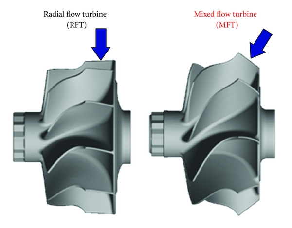
An axial turbine, On the other hand, is a turbine that uses a fluid flowing in a perpendicular direction to the blades of a rotor rather than flowing in the same direction. The windmill is the most typical type of axial turbine. In a windmill, the blades of the rotor are created to trap wind when blowing through the rotor blades. John B. McCormick combined two types of turbines into a single turbine and thus, increased the efficiency of the unit. Energy efficiency is a rapidly growing topic around the world, and any design that enhances the energy efficiency of a system is valuable.
Advantage of Mixed Flow Turbines over Axial Turbines and Radial Turbines
The efficiency of the axial turbine is approximately 70% to 75%. This is because there is a gap between the rotor blades for fluid to move through. The only way to capture all the air blowing at a windmill was to make the windmill a complete, solid circle. By the way, if the windmill was a complete solid circle, the air would not be caught in a useful way by the turbine, which means that there would be no axial turbine with 100% efficiency.
The radial turbine has an efficiency of about 80%. The reason for the efficiency to be lower than 100% is a phenomenon called “secondary flow.” This occurs when fluid on the blade edge separates from the blade and no longer contributes to turning the rotor. Again, consider the toilet example; when you flush the toilet, the water outside the bowl sometimes does not circulate perfectly with the rest of the water. This portion of water is known as the secondary flow of the toilet water. The more the secondary water is in the flow, the less water contributes to turning the fan. Therefore, the efficiency decreases.
When both of these designs are combined, the efficiency rises to about 85% to 90% because, in a mixed flow turbine, the fluid enters radially, the secondary flow is minimized, and the efficiency of the axial turbine part is maximized with a forced fluid flow. It may not seem like a significant increase in efficiency, but on a large industrial scale that costs millions of dollars in energy, even a small increase in efficiency can save a great deal.
Application of Mixed Flow Turbine
The mixed flow turbine was such a desirable design that it is still used today. For example, modern car turbochargers utilize mixed flow air intake systems to maximize the quantity of air entering the engine cylinders. More air means more explosions in the engine compartment, which in turn produces more power output.
When the engine speed increases, it needs more air at a higher rate. The turbocharger helps to meet this need for more air since the higher the number of engine revolutions (rotational speed), the more times the fan rotates in the turbocharger. The turbocharger is an essential component in many types of auto racing, even though it uses a design that is astonishingly more than 100 years old.
Mixed flow Turbochargers
Due to the increasing demand for improved fuel consumption of passenger cars, part-load performance is essential for designing and engineering automotive turbocharger turbines. In an automotive drive cycle, it is desirable to have a turbine that can obtain more energy at high-pressure ratios and lower rotational velocities.
It is usually found that radial turbines have maximum efficiency at speed ratios of 0.7. However, at high-pressure ratios and low rotational velocities, the blade speed ratio is low, and the rotor experiences high values of positive incidence (the difference between flow angle at the inlet and blade angle at the leading edge of the rotor) at the turbine inlet. According to primary considerations, mixed flow turbines provide substantial advantages for such purposes.
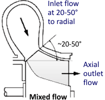
Mixed flow turbines, which are successfully used in modern gasoline applications, have advantages, including a flat efficiency characteristic curve over a wide range and reduced inertia. Using mixed flow turbines in automotive turbocharger applications makes it possible to achieve more favorable efficiency characteristics than radial turbines. Mixed flow turbines are capable of having lower inertia which positively provides a transient response while maintaining allowable stress limits. For a mixed flow design, stress levels in the turbine back disc are lower, which supports higher speeds.
Mixed Flow Hydraulic Turbine
If you want to learn about the basics of water turbines, visiting this link will help you a lot. In a mixed flow reaction water turbine of the propeller type, the water flows through the runner first radially and then axially relative to the turbine axis. The water moves from the casing of the turbine to the guiding mechanism of the stator. The shape of the draft tube is usually curved.
Mixed flow turbines have the highest optimum efficiency of all hydraulic turbine types. However, the performance characteristic curves of mixed flow turbines are not as flat as that of adjustable-blade turbines. Consequently, when the head varies greatly and the number of units is small in hydraulic power plants, mixed flow turbines are inferior to turbines with adjustable blades for power generation. On the other hand, the cavitation features of mixed flow turbines are remarkably better than those of adjustable-blade turbines.
Because the blades of mixed flow turbines are rigidly connected to the upper and lower rims, the mechanical strength of the turbines is high, and therefore, they can be applied for heads of up to 600 meters. For heads more than 150 meters, Only mixed-flow hydraulic turbines are used. Also, for heads in the range between 45 and 150 meters, mixed flow turbines are efficient in hydraulic units in which there are small head variations and large numbers of turbine units.
Mixed flow turbines with a high specific speed are utilized for low heads, and for high heads, those with a low specific speed are applied. In 1974, the greatest mixed flow hydro turbines in terms of power and diameter of the runner were installed at the Krasnoiarsk Hydroelectric Power Plant in the USSR. The diameter of the runner of these turbines is 7.5 meters, and the power is more than 500 megawatts; they are built to operate at a maximum head of about 100 meters.
N_{s}=\frac{n\sqrt{P}}{H^{\frac{5}{4}}}
P is the turbine power (kW), n is the rotational speed (rpm), and H is head (m).
Francis Turbine
Francis turbines are used extensively due to their wide range of hydraulic heads, from three to 600 meters. In the high heads, the output and the flow rate must be large; otherwise, the runner will be too small for reasonable manufacturing. At the low heads, propeller turbines are normally more efficient except for small power outputs.
Francis turbines are excellent in the medium range of heads from 120 to 300 meters and are offered in a wide range of sizes and designs. They can have horizontal or vertical shafts. Vertical-shaft turbines are used in machines that have diameters of about two meters or more and typically occupy less space than horizontal machines. This allows greater submergence of the turbine runner with minimal deep excavation and makes the generator mounted on the tip easily accessible for maintenance.
Horizontal axle units are more compact for smaller sizes, and this creates access to the turbine easier. However, as size increases, it becomes more difficult to remove the generator for repair.
The most common design of Francis turbine has a welded, or cast-steel, spiral casing. This part helps distribute water evenly across all inlet gates, which are up to 24 pivoted gates or guide vanes used. Depending on the power output desired, the gates work from fully closed to fully open. Most of them are driven by a standard regulating speed ring and connected to the pin in such a way that if one of the gate passages is blocks by debris, no damage will occur. The regulating ring is turned by one or two oil-pressure servo motors controlled by the speed governor.
Slow and high power units have an almost radial set of blades, while in fast and low-power units, the curved blades extend from the radial inlet to nearly the axial outlet. After determining the overall blade dimensions (blade height and inlet and exit diameters), the blades are designed for the smooth flow of water at the inlet and a minimum water swirl at the outlet.
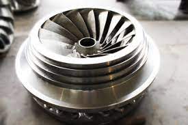
The number of blades can be from 7 to 19. Runners of low head units are generally made of cast mild steel. However, sometimes stainless steel protection is added at places where they are subjected to the risk of cavitation. All stainless steel structures are usually more used for high heads.
Large units can be welded on-site, applying a suitable combination of different pre-made steel sections to provide water passages with precision and perfect shape. Francis turbines allow the construction of very large and high-output units.
Deriaz Turbine
A Deriaz mixed flow turbine uses swiveled, variable-pitch blades to improve performance at part loads in medium-sized units. The Deriaz design has been applicable to higher heads as well as for some pumped storage applications. It has the benefit of lower runaway (sudden loss of load) speed than Kaplan turbine, which leads to remarkable savings in generator costs. However, very few Deriaz turbines have been built. The first 22,750 kilowatts, a non-reversible Deriaz turbine with a head of 55 meters, was established in 1958 at an underground station at Culligran, Scotland.
Buy Equipment or Ask for a Service
By using Linquip RFQ Service, you can expect to receive quotations from various suppliers across multiple industries and regions.
Click Here to Request a Quotation From Suppliers and Service Providers
Read More on Linquip

