The main parts of centrifugal pumps can be divided into the wet end and the mechanical end. The wet end parts of the pump include those that provide the hydraulic performance of the pump: the impeller and the casing. Sometimes the first radial bearing can be water-filled. In this case, the bearing can belong to the wet end. The mechanical end of the centrifugal pump consists of components that support the impeller inside the casing: the pump shaft, shaft sleeve, sealing, and bearings.
If you would like to learn more about centrifugal pumps, it is best to visit Linquip’s website, where you can discover all the information that you may need. We have a group of experts at your disposal if you have any questions regarding centrifugal pumps, and they will be happy to assist you in any way they can. As a first step, you may want to read Linquip’s article titled “Centrifugal Pump: Working Principles, Function & Diagram” to gain a basic understanding of how these pumps operate.
Do you have any previous experience working with centrifugal pumps? In Linquip, you will find a comprehensive list of Centrifugal Pump Products that will allow you to find the exact product you seek. How about now? What type of centrifugal pump are you looking for? Linquip offers you free access to all Centrifugal Pump Devices for Sale available on the website, which you can find through the link provided here. On top of that, using Linquip, you will be able to receive a free quote or inquiry regarding the prices of centrifugal pumps from all Centrifugal Pump Suppliers and Companies available on the Linquip platform.
This article focuses on the main part of centrifugal pumps, but first, we will discuss the principles of centrifugal pumps.
⇒ View a Comprehensive List of Centrifugal Pumps for Sale and Their Suppliers ⇐
Basics of Centrifugal Pumps
A Centrifugal pump is a hydraulic turbomachine that converts mechanical energy into hydraulic energy using centrifugal force applied to the fluid. This type of pump is the most commonly used pump to transfer fluids from a lower level to a higher level. It is used in a wide range of applications, including municipal (water and wastewater plants), agriculture, power plants, petroleum and pharmaceutical industries, mining, chemical industry, and many more.
When a mass of liquid rotates by an external force source, it moves away from the axis of rotation, and the added hydraulic pressure to the liquid enables it to reach a higher level. Centrifugal Pumps can be utilized for both viscous and non-viscous liquids due to their high efficiency.
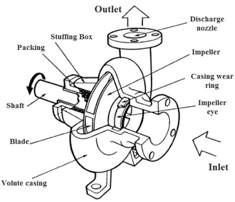
Working of Centrifugal Pumps
First, the operation of a centrifugal pump needs the priming step. It means that the suction pipe casing of the pump operates so that all the air from the position of fluid with the liquid which is to be pumped is driven out, and no air remains. The importance of this step is due to the point that the pressure produced by the centrifugal pump is directly proportional to the density of the fluid in contact with it.
Then, the electric motor starts to rotate the impeller while the delivery valve is still kept closed. After opening the valve, the liquid is made to flow in a direction radially outward through the vanes of the impeller toward an outer circumference with high velocity. Due to the centrifugal action, a vacuum is created. This causes the liquid to flow from the sump to rush through a suction pipe to the eye of the impeller.
Main Components of Centrifugal Pumps
After a brief introduction of centrifugal pumps and how they work, we will introduce the parts of centrifugal pumps in detail. As mentioned in the introduction, in general, these components can be classified into two groups: wet end and mechanical end.
The wet end of a centrifugal pump consists of those parts that determine the pump hydraulic performance.
However, the mechanical end includes the parts that hold the impeller within the casing and seal the casing where the pump shaft passes through. Additionally, these parts enable the impeller rotation that allows the wet end to create flow and pressure.
Wet End
In short, the impeller turns at high speed and adds speed to the water. The impeller is located within the casing. The casing is responsible for converting the velocity produced by the impeller rotation into pressure. There are various types of impellers and casings.
Casing
The casing is the shell or housing protecting and supporting the components. In pumps, the casing is a significant component to prevent leakage and even maintain pressure.
There are generally two basic types of casings: volutes and diffusers.
Volutes
When a liquid enters the outer diameter of an impeller, the volute acts to capture its velocity and convert the velocity into pressure. The following figure shows a schematic structure of a centrifugal pump with a volute casing.
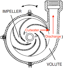
The part of the volute that extends most adjacent to the impeller is named the cutwater. Starting from the cutwater and moving counter-clockwise, the distance between the impeller and the volute gradually increases. This causes the pressure to increase inside the volute as the distance increases. Finally, as you reach the point directly next to the cutwater proceeding clockwise, the pressure is at its maximum, and then, the water comes out of the casing.
Diffusers
Rather than cutwater, diffusers have vanes. While the volutes have only one or two points where the casing edge approaches the impeller to create pressure, diffusers usually have many vanes. In the schematic below, the number of vanes is ten.
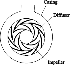
While an impeller is positioned in the center of a volute, in a diffuser casing, an impeller is generally located directly adjacent to a diffuser and forces water into the vanes. The working principle of a diffuser is similar to a volute. Diffuser vanes are placed so that they start near the outer edge of the impeller and gradually extend away from the periphery of the impeller.
Impellers
Impellers are the rotating parts in centrifugal pumps equipped with vanes or blades which turn and push fluid within the pump. These components are crucial to converting energy derived from a source.
There are three ways to classify impellers: Specific speed, design, and the vanes positions.
Specific Speed
Specific speed (Ns) is the speed at which an impeller with a geometrical similarity to the model but with a diameter of 1 meter produces a flow of 1 kg/m3 and 1 meter of total dynamic head. This value describes the relationship between the impeller flow and the output head. For a centrifugal pump, it is expressed as:
n_{s}=\frac{nQ^{1/2}}{H^{3/4}}
Q and H are mass flow rate (kg/m3) and head (m). Also, n represents the rotational speed of the impeller in rpm.
Accordingly, centrifugal pumps are classified into radial, mixed, and axial flow pumps.
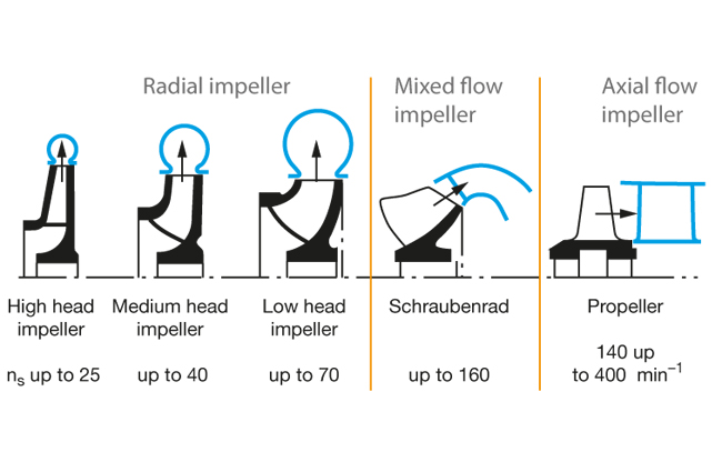
In an axial flow impeller, the fluid flows parallel to the shaft. These impellers are also called propellers. They are applicable for high flow and very low-pressure conditions. However, in a radial flow impeller, the fluid flows perpendicular to the shaft. Radial flow pumps are usually utilized in multi-stage centrifugal pumps. Also, mixed flow pumps operate part radially and part axially.
Diffuser elements in radial casings (e.g., volute casings) need to become larger as specific speed increases until the flow can be directed through the impeller radially. Finally, at high specific speeds, the flow can only leave axially.
Design
This classification method relates to specific speed since the specific speed has an important effect on the physical design of the impeller.
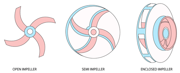
Open and Enclosed Impellers
Impellers can be designed with or without a shroud or covering. Enclosed impellers use a top and bottom shroud. However, impellers without any shroud are called open impellers.
Also, in some special pumps, such as vortex impellers, there are single-shroud impellers in solids-handling pumps. These designs only have a top shroud, and the vanes are quite open to the pumped liquid. Single-shroud impellers are suited for purposes where there are a large number of solids that may clog a shrouded impeller. However, the efficiency of single-shroud vortex impellers is much lower than enclosed impeller designs.
Single- and Double Suction Impellers
A single-suction design means that there is a single part of the impeller that is designed to absorb the water. Also, there is another design of impellers in which the suction takes place from both sides of the impeller. The following schematic figure illustrates the difference between the single- and double suction impellers.
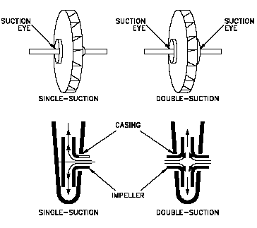
A double-suction design is more balanced than a single suction design because the two-sided suction of liquid balances the axial forces applied on the impeller and transferred to the pump bearings through the shaft.
Vane Design
Some impellers have multiple vanes and small internal clearances. These are usually designed for water services between the radial and Francis-vane (an impeller type between the radial and mixed flow) specific speed ranges. However, other impellers have only one or two vanes as well as large internal clearances, which are usually called solids-handling impellers. They generally operate in the ranges between the Francis-vane and mixed-flow pumps.
Other types are designed with a single vane and without a lower shroud (screw impellers) or with vanes that are not extended very away down into the pumped liquid (vortex impellers). These both are designed for the utilization of a high concentration of solids.
Other types of impellers do not have a shroud at all, top or bottom (e.g., in the axial-flow field).
Vanes Positions
Accordingly, Impellers can be open, semi-open, and closed.
Open Impellers
In open impellers, the vanes are installed free on both sides. This type of impeller is structurally weak. The typical use of open impellers is in small-diameter, low-priced pumps and those handling suspended solids.
Semi-Open Impellers
The vanes in semi-open impellers on one side are free and enclosed on the other side. Thus, the shroud provides mechanical strength. They also work with higher efficiencies than open impellers. They can be applied in medium-diameter pumps containing liquids with small concentrations of suspended solids. An important feature of semi-closed impellers is a small clearance existing between the impeller vanes and the casing.
Enclosed Impellers
The vanes of enclosed impellers are placed between two discs, all within a single casting. They operate with high efficiencies applicable in large pump units requiring low Net Positive Suction Head. The enclosed impeller is a more complex and costly design because of bothering the impeller construction and the additional wear rings needed.
Mechanical End
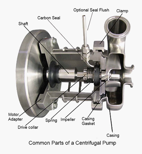
The mechanical part of a centrifugal pump includes the shaft, shaft sleeve, seals, and bearings.
Shaft
The impeller is attached to a shaft. The shaft is often made of steel or stainless steel to support the impeller. The sizes of the shafts must be measured accurately. An undersized shaft may increase pump vibration, reduce bearing life, cause shaft breakage, and shorten the overall pump life. On the other hand, an oversized shaft can unnecessarily increase the pump costs.
Shaft Sleeve
Usually, a portion of the shaft located below the seals is covered with a shaft sleeve. The shaft sleeve is made of a metal, generally bronze or stainless steel. It is designed to operate with the ability to slide or thread on the shaft. The shaft sleeve is applied to properly position the impeller on the shaft as well as to protect the shaft.
Seals
The place where the shaft passes through the casing is the stuffing box. Sealing must be utilized to seal the distance between the shaft and the stuffing box wall.
Mechanical seals are different in performance, design, and cost. The simplest seal includes only a few elements: gland, stationary seal ring (or mating ring), rotating seal ring (or primary ring), and spring.
Gland
The gland is located around the shaft of the pump and bolts to the face of the stuffing box directly on the pump casing.
Stationary Seal Ring
The stationary seal ring is sealed to the gland and fixed just around the pump shaft by the gland.
Rotating Seal Ring
The rotating seal ring is sealed to the shaft using an elastomeric element and is pressed against the stationary seal ring by a spring.
Spring
The spring exerts pressure on the rotating seal ring by pressing against a retaining clip or the collar that is fastened to the pump shaft.
As the stationary face is sealed to the gland, and the rotating face is sealed to the shaft, the only passage for the liquid to leak from the stuffing box is to flow between the rings being pressed together by the spring.
By spinning the pump shaft, the rotating face turns against the stationary face. A small amount of the pumped liquid goes between the faces but evaporates because of the heat produced by the rotating seal faces. This small portion of the liquid is sufficient to hold the seal faces cool and lubricated. By the time the seal faces are clean, smooth, and lubricated, they can eliminate almost all leakage between the shaft and the stuffing box wall.
Bearings
In general, centrifugal pumps are provided with standard ball-type anti-friction bearings lubricated by grease or oil. These bearings are the same as those used in other objects such as electric motors, roller skates and automobiles.
The shaft is held in place by the bearings that must be designed so that they can withstand all the loads generated by the rotation of the impeller. Also, they have to be sized to offer a suitable service life. Bearing failures are a common reason for pump downtime. Therefore, engineers and end-users are often interested in the specific details about the design of the bearing configurations.
There are various types of bearings:
Roller bearings
These bearings utilize cylindrical shape rollers between moving components. This reduces friction and helps support radial and axial load.
Ball Bearings
Ball bearings apply balls to help the movement of parts. Although uncomplicated in design, they are proper for high speeds and easy to maintain.
Sleeve Bearings
Sleeve bearings are applicable for high speeds. These bearings are only ideal for radial loads and are designed to float.
Babbitt Bearings
This bearing is a type of sleeve bearing coated in Babbitt metal. It is commonly used in pumps, turbine generators, fans, and motors.
Pivot Shoe Bearings
Pivot shoe bearings, also called tilt shoe bearings, are suitable to handle axial loads and act as a thrust bearing in high-powered centrifugal pumps.
What Type of Motor Is Used to Power Centrifugal Pumps?
DC shunt motors are almost constant speed motors. So, it is used to drive constant speed line shafts, lathes, centrifugal pumps, paper-making machines, and small printing presses, among others.
What Does Pump Coupling Mean?
Motor drive shafts are connected to rotating pump shafts by pump couplings, which enable the motor to transmit power to the pump efficiently. A close-coupled pump does not require a separate coupling since the motor is directly attached to the pump on a single shaft.
Download Parts of Centrifugal Pumps PDF
For your convenience, we included the option to download this document in PDF format. You can get started by clicking the following link.
Buy Equipment or Ask for a Service
By using Linquip RFQ Service, you can expect to receive quotations from various suppliers across multiple industries and regions.
Click Here to Request a Quotation From Suppliers and Service Providers
Read More on Linquip
- Working Principle of a Centrifugal Pump
- Diaphragm Pump Parts
- Types of Centrifugal Pumps: All Classification & Working Principles
- What Is a Multistage Centrifugal Pump Used for
- Parts of Oil Pump
- 7 Parts of Gear Pump and Function + Diagram & Applications
- 10 Parts of Reciprocating Pumps + Function, Application and Working
- Types of Pump Casings (In Centrifugal Pumps & Others) + Pros & Cons
- All You Need to Know About Centrifugal Pumps
- Top Dosing Pump Manufacturers and Suppliers in 2022
- Top Water Pump Manufacturers and Suppliers in 2022
- The 7 Best RV Water Pump In 2022 (Clear Guide + Review)
- The 10 Best Electric Air Pump in 2022 (Clear Guide)
- The Best HVAC Vacuum Pump in 2022 (Clear Guide)
- Different Types of Rotary Pumps + PDF
- The 5 Best Well Pump in 2022 (Clear Guide)
- The 10 Best Condensate Pumps of 2022: A Complete Guide
- 13 Parts of Concrete Pump with Name & PDF
- 5 Types of Concrete Pumps + PDF
- 6 Type of Sump Pump and Which Are Better to Buy?
- 6 Parts of Pool Pump + Diagram & PDF
- 20 Parts of Submersible Pump + PDF
- What Is a Demand Pump and How Does It Work? (Clear Guide)
- 12 Parts of Sump Pump + Diagram


A lot of content has been displayed.Thanks to operamin
Hi Pous. Which Content Exactly?