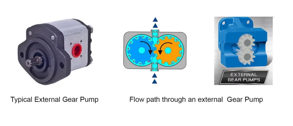
This post will explain in detail the main parts of gear pump, one of the most popular positive displacement pumps. This pump delivers continuous flow through its operation. Using gear meshes, a gear pump converts mechanical energy into fluid energy. The pump is effective for prolonged usage of viscous liquids, such as oil, without any need for priming.
The Linquip website is the most reliable resource you can turn to if you want to learn everything you need to know about gear pumps. In case you have any inquiries about gear pumps, our experts are always available to assist you. A good starting point for understanding gear pumps is Linquip’s article, “Gear Pump: Working Principles, Function & Diagram“.
Have you worked with gear pumps before? The Gear Pumps Products that we have listed on our website will allow you to choose the exact item you are looking for. If you had to choose, what kind of gear pump would you require? Linquip is proud to offer free access to all of the available Gear Pump for Sale that can be found on Linquip’s website. We at Linquip offer you a chance to ask for a free quote or inquire about gear pump prices from all the Gear Pump Suppliers and Companies that you wish to contact.
To begin, let’s look at the basics of a gear pump, including its function, diagram, and applications. Next, we will take a closer look at each component. This article is recommended for those who are interested in learning all the essential points about gear pumps.
⇒ View a Comprehensive List of Gear Pumps for Sale and Their Suppliers ⇐
An Introduction to Gear Pump
Gear pumps are rotary displacement pumps. The positive displacement pump (also called displacement pump or PD Pump) physically compresses a fluid through mechanical action, in contrast to a centrifugal pump which converts velocity into pressure.
Johannes Kepler invented gear pumps in the early 17th century. They are commonly used for hydraulic power applications as well as for applications involving high viscosity liquids. They are self-priming since they can pump air like all positive displacement pumps.
Gear pumps are generally of two types. In one of the designs, two identical gears engage with one another; this design of the pump is known as an external gear pump. In the second design, one gear is placed inside another gear. This type of pump is called an internal gear pump.
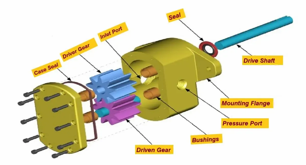
There are usually two gears in a gear pump; a driver gear or the power gear and a driven or the idle gear. A driver gear is also called a master gear, while a driven gear is called a slave gear. The driver gear is attached to one or more prime movers or mechanical energy sources. Electric motors, IC engines, or human hands are all used for rotating the driver gear.
Fluids move inside a gear pump when the interlocking gears enclose a fixed volume of fluid and then transfer it as the gear rotates. With this pump, a continuous, pulse-free flow rate is supplied proportional to the rotational speed of the gears.
In chemical installations, gear pumps are also widely used, to pump fluids with a high viscosity. Gear pumps are primarily used for developing high pressure.
The maximum working pressure for a gear pump is typically 210 bars (21,000 kPa), and the maximum speed is 3,000 rpm. There are some manufacturers that produce gear pumps that have higher speeds and pressures. However, these pumps are often noisy, so special precautions need to be taken.
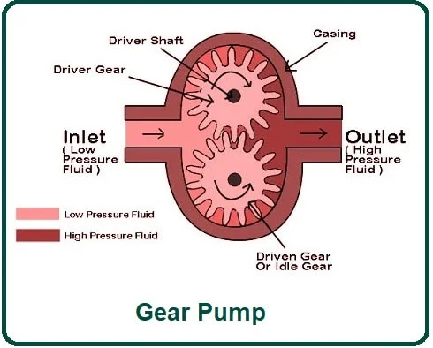
Working Principle of Gear Pump
A gear pump traps fluid on its suction side and discharges it at a higher pressure on the discharge side. It is similar to the operating principle of an internal gear pump for an external gear pump. Both principles will be discussed separately for clarity.
External Gear Pumps
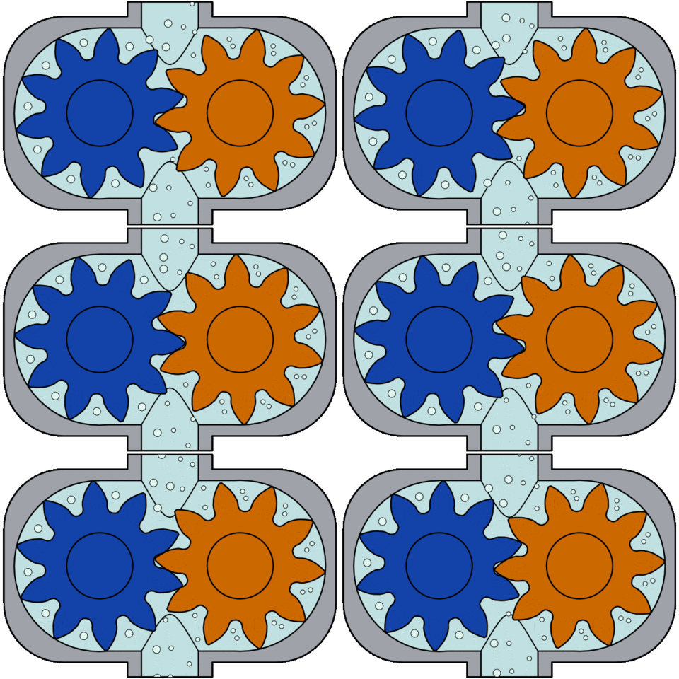
The liquid enters the pump at the suction end. On the suction side, as the gears turn, the volumetric space between gear teeth increases. The negative suction pressure within the cavities allows fluid to enter the spaces/cavities between the teeth. During further rotation of the gears, the fluid trapped within the cavities is forced to flow between the gears and casing.
The gears progress towards the discharge side as they carry on the rotation. Due to the increase in the gap between gears and casing, the fluid exits from the cavities. While the gears are spinning, they become interlocked, causing any remaining fluid in the cavities to be squeezed out. Upon separation of the gears on the suction side, fluid can enter the vacant spaces, and thus the cycle can be repeated.
Internal Gear Pumps
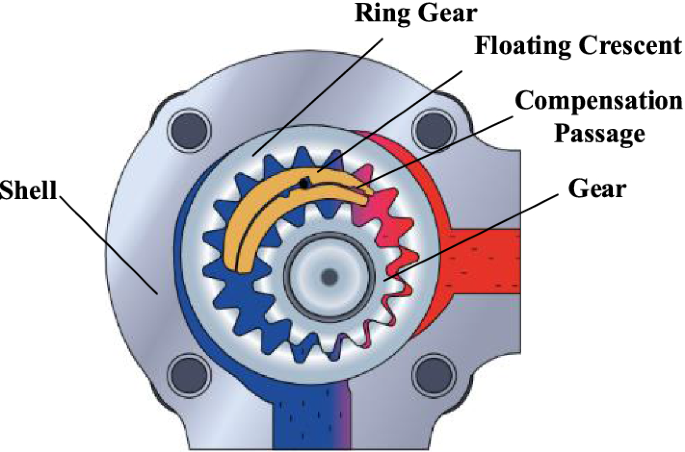
Drive mechanisms (such as electric motors, etc.) rotate the rotor gear (the internal gear). Idler gears (external gears) rotate along with the rotor gear as it rotates. The fluid enters the pump on the suction side and moves into the cavities between the rotor and idler.
As the gears continue to rotate, they are separated by a stationary crescent seal. There are cavities between the rotor gear and inner crescent surface, as well as between the idler gear and outer crescent surface where fluid is trapped. With each turn of the gears, the gear teeth from both gears get closer together. Once the gears mesh, fluid begins to flow from the cavities and exits the pump; the whole process then is repeated.
Although alternative designs for internal gear pumps lack a crescent seal, their operating principle is much the same.
Applications of Gear Pump
Gear pumps are usually used to pump oil, paints, resins, or food products that have a high viscosity. In any application that requires precise dosing or high-pressure output, they are the best choice. In situations where the supply is irregular, gear pumps are also preferred because their output is not much affected by pressure.
Below are some examples of typical external and internal gear pump applications:
- Automotive fuels and oils.
- Hydraulic oils.
- Solvents and alcohol.
- Hot oil circulation on a small scale.
- Paints, resins, and polymers.
- Liquid soap.
- Edible foods such as corn syrup, animal food, and peanut butter.
Components and Construction of Gear Pump
7 Parts of Gear Pump are:
- Prime Mover
- Driver gear
- Driven gear
- Housing
- Inlet port or suction side
- Outlet port or discharge side
- Pressure relief valve or safety valve
- Seal
Gear pumps consist of the following major components:
1. Prime Mover
The gear pump relies on a prime mover to drive the shaft that contains the power gear. It can be powered by manual labor, an IC engine, or an electric motor.
2. Driver or Power Gear
The driver or power gear is connected to the prime mover. This gear rotates with the power of the main motor.
3. Idler or Driven Gear
A driven gear meshes with a power gear. This gear rotates as the power gear does.
4. Housing
A hydraulic gear pump housing contains both the power gear and the idler gear.
5. Inlet Section
This is the part of the pump that takes liquid into the pump. It is the inlet section that gets low-pressure liquid into the pump.
6. Outlet Section
The gear pump has this part that delivers compressed liquid to the area in question. The high-pressure liquid exits from the pump at this point.
7. Pressure Relief Valve or Safety Valve
In order to prevent the pump from being damaged, this valve is installed on the outlet section so that it can release fluid in the event of excess pressure.
Design of a Gear Pump
Among the most popular pumps used in hydraulics systems today are positive displacement, external gear pumps, which are versatile, strong, and long-lasting.
They are simple in construction compared to other types (piston, orbital, etc.) and are therefore cost-effective to purchase and service.
In addition to supporting the heavy-duty operation, these hydraulic gear pumps and motors deliver high hydraulic power, provide good hydraulic, mechanical, and volumetric efficiency, are quiet, and have compact dimensions as well as low weight/power ratios. They are well suited for both industrial and mobile industries.
An aluminum bushing guides a gear set supported by a body, a flange secures the gear set, and a cover covers the entire assembly.
To strengthen the setup, a seal ring is incorporated into the shaft of the driving gear that projects beyond the flange. An elastic securing ring is then inserted between the two rings.
A special aluminum alloy provides a high-strength body that minimizes deformation even when subjected to high pressure.
Depending on the model series type, flanges and covers are made of cast iron or aluminum alloy, manufactured through continuous flow casting, and are phosphated for a final finish.
A special grade of steel is used for the gears. A case-hardening and quench-hardening process are used in their manufacturing process. The gears are polished to a high level of finish by grinding and fine finishing. The motor operation is quiet and low-pulsation with a good tooth profile design and geometric proportions.
A special alloy of low-friction anti-friction aluminum has been developed and made from die-casting that is both strong and has excellent anti-friction properties. Additionally, anti-friction DU bearings were installed with tight tolerances.
By creating special and symmetric compensation zones onto the bushings and insulating them with a special anti-extrusion ring, the bushings can move freely axially and radially, which is proportional to the motor pressure. In this way, internal leakage is greatly reduced, delivering excellent performance (both mechanically and from a total efficiency point of view) and ensuring proper lubrication of pump moving parts.
Operational Characteristics
In order to enhance the performance of a gear pump, friction between its parts needs to be reduced. During friction, heat is generated, which in turn causes a gear pump’s components to expand physically. Due to their tight mechanical clearances, gear pumps, particularly external gear pumps, are susceptible to thermal expansion damage. For instance, gear teeth might become misaligned, which would result in wear, leaks, and a consequent decrease in efficiency. An improperly aligned gear pump may seize (be unable to rotate) in severe cases.
It is common for the fluid being pumped to serve as lubricant for the pump’s internal components. As a result, most gear pumps are inefficient when dry (without fluid flow) for prolonged periods of time.
A gear pump is most efficient when running at its maximum design speed. A lower revolution per minute (rpm) will result in lower pump efficiency.
The tight tolerances of gear pumps mean they are not a good choice for pumping liquids with solids since this would damage the gears and other components of the pump. Furthermore, gear pumps generally do not achieve as high flow rates as centrifugal pumps when operating under lower discharge pressures. Also, gear pumps are usually run at lower speeds than centrifugal pumps (generally 300-600 RPM), requiring gear reducers or belt drive systems. Higher viscosity liquid requires a gear pump with a lower rotation speed.
A gear pump is a positive displacement pump, so its flow rate is relatively low (a “fixed” flow rate) regardless of whether the discharge pressure increases or decreases. Consequently, with an increase in discharge pressure, horsepower requirements will increase. As viscosity increases, the horsepower required for a given gear pump will also increase (this results in an increase in discharge pressure in the piping system due to increased friction losses caused by the more viscous liquid on the walls of the pipes and other plumbing components).
The Right Relief Valve for a Gear Pump
There are several ways pressure may build in a positive displacement pump, including blocked discharge lines and closed isolating valves. A positive displacement pump continues to generate flow and pressure until something fails, unlike centrifugal pumps that may experience cavitation phenomenon under such circumstances. Sometimes it’s the pump that needs to be repaired or replaced, which is costly.
Using relief valves within positive displacement pumps can be a useful measure. When the discharge line of the pump is under pressure, these valves divert the fluid flow, preventing failure. Relief valves can be internal or external.
Internal Relief Valves
An internal relief valve is an integral part of the pump’s construction.
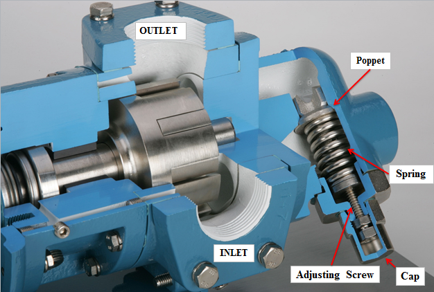
During pressure buildup within the discharge line and on the discharge side of the pump casing, force is applied to the surface of the poppet. The pressure that exceeds the tension of the spring, which is set manually via the adjusting screw, causes the spring to compress, allowing fluid to flow around the poppet. Thus, the channel becomes the path of least resistance, allowing fluid to flow continuously through the pump casing and valve body.
Since the fluid has a limited flow path, it heats up quickly due to pressure and friction. Heat leads to a decrease in viscosity and an increase in slip. Depending on the fluid, a rise in temperature could also lead to flashing (vaporization of the fluid) or other undesirable effects.
Using Internal Relief as your primary safety relief is not recommended. These valves are an excellent solution for blockages in the discharge line or other unexpected situations. Internal relief valves are ideally not used as a means to divert flow purposefully and should serve more as redundant safety mechanisms.
External Relief Valves
As with the internal relief valve, the external relief valve diverts fluid flow to relieve excessive pressure in the discharge line. However, instead of continuously passing through the pump, the fluid is diverted back into the feed tank or drawn into the suction line upstream of the pump. In contrast to internal relief valves, this allows heat to escape the liquid before it returns to the pump.
If a pump is going to be isolated but not shut down, external relief valves should be used. These valves, which have been described above, are used as a long-term pressure relief method due to their nature.
Download Parts of Gear Pump PDF
For your convenience, we have included the option for you to download the PDF version of this article. To get started, please click on the following link.
Buy Equipment or Ask for a Service
By using Linquip RFQ Service, you can expect to receive quotations from various suppliers across multiple industries and regions.
Click Here to Request a Quotation From Suppliers and Service Providers
Read More on Linquip
- Gear Pump: Working Principles, Function & Diagram
- 10 Parts of Reciprocating Pumps + Function, Application and Working
- Parts of Water Pump
- Parts of Centrifugal Pumps
- Diaphragm Pump Parts List + Function & Application
- 10 Parts of Hydraulic Pump + PDF & Function
- 20 Parts of Submersible Pump + PDF
- 6 Parts of Pool Pump + Diagram & PDF
- QUICK GUIDE: TYPES OF GEAR PUMPS
- The 5 Best Air Source Heat pump in 2022 (Clear Guide)
- 7 Best RV Water Pump In 2022 (Clear Guide & Review)
- The 10 Best Electric Air Pump in 2022 (Clear Guide)
- The Best HVAC Vacuum Pump in 2022 (Clear Guide)
- 9 Different Types of Rotary Pumps + PDF
- The 5 Best Well Pump in 2022 (Clear Guide)
- The 10 Best Condensate Pumps of 2022: A Complete Guide
- 13 Parts of Concrete Pump with Name & PDF
- 5 Types of Concrete Pumps + PDF
- 6 Type of Sump Pump and Which Are Better to Buy?
- 12 Parts of Sump Pump + Diagram
- 8 main Parts of Piston Pump and Function + Work & PDF
- 7 Parts of Screw Pump: Advantages and Disadvantages
- Types of Centrifugal Pumps: All Classification & Working Principles

