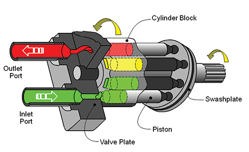
Multiple moving and static parts of hydraulic pump work together to energize the fluids from lower pressure to higher. In this article, we have discussed a general overview of hydraulic system components. To begin with, we would rather explain the basics of hydraulics so that you can gain a clearer understanding of these kinds of hydraulic machines.
The Linquip website is the best place for you to find all the information you need to know about hydraulic pumps. Our experts are on hand to assist you if you have any questions regarding hydraulic pumps. If you would like to gain a basic understanding of hydraulic pumps, you can start by reading Linquip’s article, ” Hydraulic Pump: Working Principles, Function & Diagram“.
Do you have any experience with hydraulic pumps? We have a selection of Hydraulic Pumps Products that will let you find the exact thing you are looking for. Which type of hydraulic pump are you currently in need of? Linquip offers free access to all available Hydraulic Pump Devices for Sale available on the website. Linquip gives you the opportunity to ask for a free quote/inquiry for hydraulic pump prices from all Hydraulic Pump Suppliers and Companies.
⇒ View a Comprehensive List of Hydraulic Pumps for Sale and Their Suppliers ⇐
A Brief Description of Hydraulic Pump
Several dynamic machines rely on hydraulic pumps for power. Large amounts of oil can be pumped through hydraulic cylinders or hydraulic motors by hydraulic pumps. Essentially, the pump turns mechanical energy from the drive (torque or speed) into hydrostatic energy (flow or pressure). Hydraulic machines use a pump and can do a variety of jobs, including lifting, lowering, opening, closing, and rotating components.
During its operation, a hydraulic pump performs two functions. Firstly, its mechanical action produces a vacuum at the pump inlet, which allows atmospheric pressure to force liquid into the pump’s inlet line from the reservoir. Second, the mechanical action of the pump pushes this liquid into the hydraulic system via the outlet.
The pump does not generate pressure, but it does move liquid. It provides the flow necessary for the formation of pressure, which is a function of resistance to fluid flow in the system. If a pump is not connected to a system, its outlet pressure is zero. In addition, when a pump is delivered into a system, the pressure will only rise to the level necessary to overcome the load’s resistance.
Hydraulic pump is a class of positive displacement pumps that can be used for fluid power applications. The system uses hydraulic fluid to supply power to different parts of the machine, such as motors, rams, cylinders, etc. For positive displacement pumps, the hydraulic pumps are primarily used to provide hydraulic oil to the piston so that it can move quickly forward and backward. An example of a hydraulic pump is the power steering pump in cars. Oil pumps in transmissions are another type of hydraulic pump.
In addition, hydraulic pumps are powered by an electric motor and equipped with pressure relief valves to prevent over pressurization.
Usually, these pumps are used in applications with large flow rates and low pressure. They do so because they drive low-pressure fluids at high speeds and quickly move large quantities of fluids.
Hydraulic systems involve the transmission of energy from an electric motor to actuators such as hydraulic cylinders using fluid. Fluids moving through these systems are incompressible, and their paths are as flexible as wires.
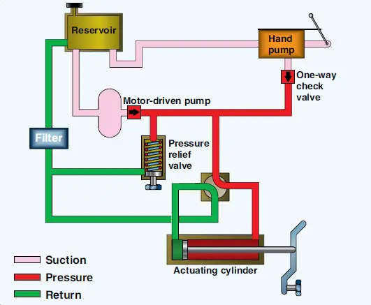
The use of these systems is primarily limited to high power densities or when loads increase rapidly. Hydraulic systems are particularly useful for moveable equipment, such as excavators, and industrial systems, such as presses.
During wind turbine operation, hydraulic systems are used to control the slope and the brakes. Hydraulic systems are also used in some cases to operate auxiliary structures (like cranes and hatches).
Function of Hydraulic Pump
Displacement is the basis of hydraulic pumps. A hydraulic pump operates as follows:
- Hydraulic pumps have two types of gear, the driver or power gear, and the driven or idler gear. Both of these gears mesh together.
- A driving shaft transmits power from the electric motor to the driver gear.
- If the driver gear begins rotating, then the driven gear moves with it as well.
- At the inlet section, a vacuum is generated as these gears move. Due to the vacuum created by this pump, fluid or oil is drawn out of a tank or reservoir.
- It has two check valves, one at the suction end and one at the discharge end. A check is intended to stop fluids from flowing backward. Fluid is sucked into this pump from the suction side, and a check valve located at the suction end facilitates fluid movement within the pump.
- Whenever the internal fluid pressure becomes greater than the external fluid pressure, the suction valve closes.
- The fluid has to pass between the gears of the pump before it can reach the till outlet valve since there is no direct route.
- As the fluid enters the pump, it is trapped between the driven and driver gears.
- When the gears are moved, the fluid or oil moves as well. Fluid flows between gears, causing its volume to decrease and its flow rate to increase.
- Once the desired flow rate is reached, this hydraulic oil or fluid is released through the discharge valve and is supplied to different parts of the system, such as pistons and cylinders.
Components of Hydraulic Pump
10 Components of Hydraulic Pump are:
- Casing
- Runner Vanes
- Shaft
- Bearings
- Sealing
- Oil Storage Tank
- Pipeline
- Electric Motor
- Hydraulic Actuator
- Relief Valve
Several main components are required for hydraulic pumps to function as the beating heart of a hydraulic system. They are described below, along with their functions.
1. Casing
The casing is the hydraulic pump’s external part designed to ensure safety for the internal parts. Some pumps use aluminum casings, while others use cast iron castings. The casing’s main purpose is to prevent fluid from splashing outside the pump. The component also prevents the hydraulic system from getting damaged if a heavy weight falls on the system.
2. Runner Vanes
There is a rotary part of the hydraulic pump known as a runner that rotates inside the pump casing. A number of vanes rotate along with the rotation of the runner. The fluid inside the pump also rotates with the rotation of the runner vanes. The result is an increase in fluid pressure. In addition, these vanes are also essential for cooling the system and lubricating it.
3. Shaft
A shaft is used to assemble the runner. A steel or stainless steel shaft is used for the assembly. The shaft size can be adjusted based on the runner.
4. Bearings
For the runner to rotate, bearings are needed. The hydraulic system and pump rely heavily on this component.
5. Sealing
Fluid leaks from the pump can be prevented by the seal. Pumps usually fail because bearing components are damaged. Bearing components can be protected from contaminants and coolants by means of a seal.
6. Oil Storage Tank
It contains non-compressible fluids (including hydraulic oil). The tank also protects the hydraulic oil from contamination. In this way, the storage tank keeps the hydraulic system in good working order.
7. Pipeline
A pipeline inside a system is easy to install, but the most important thing is that it transports hydraulic fluid between different parts of the system.
8. Electric Motor
Motors are used to drive the driving shaft inside the system. From there, the driver gear is driven. An electric motor is thus used to power the pump.
9. Hydraulic Actuator
A hydraulic actuator is a component that transforms hydraulic energy into mechanical power in order to accomplish the desired effect.
A hydraulic actuator looks like this:
- Linear movement is generated by the hydraulic cylinder.
- A hydraulic motor produces torque and rotates the cylinder.
10. Relief Valve
The relief valve controls the pressure within the hydraulic system. Different types of relief valves are available. By means of a pressure relief valve, excess fluid pressure is returned to the inlet.
Different Types and Configurations
Various hydraulic pumps are manufactured according to various requirements, including operating medium, pressure range, type of drive, etc. The general principle and configuration of hydraulic pumps vary widely. As a result, no pump can fully satisfy all requirements to an optimum level. A hydraulic pump can be of one of the following types.
Gear Pump
The gear pump is commonly used in machines such as forklifts for hydraulic fluid power. They’re an easy-to-use, easy-to-maintain solution with a simple design. These pumps range in internal and external designs.
External Gear Pump
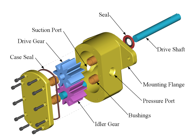
Typically, an external gear pump uses two identical gears that rotate towards each other. The gear tooth profiles, the inner walls of the housing, and the bearing block surfaces form displacement chambers. These chambers move oil from the suction side to the pressure side. A gear pump has a fixed flow rate per rotation.
Internal Gear Pump
The same is true for internal gear pumps. They have interlocking gears of differing sizes. The internal gear is the bigger gear (rotor). The smaller external gear, also referred to as the idler, rotates inside the large gear. By interlocking the two gears, pressure is applied to the liquid.
Lobe Pumps
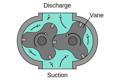
Lobe pumps are rotary external gear pumps. They have multiple lobes. In order to move fluids, these lobes spin around a parallel shaft inside the pump housing. With a gear pump, one gear drives the other, while with a lobe pump, both lobes are driven by their own drive gear outside the pump housing chamber.
These pumps can be used in industries such as biopharmaceutical manufacturing, food and beverage processing, hygienic processing, etc.
Screw Pump
Screw pumps are positive displacement pumps. This means that the liquid is being moved by consistently dislodging its space. There are two counter-rotating screws that drive the screw pump, which are designed to rotate toward each other.
In other words, it’s an axial-flow gear pump. Pumps such as this work similarly to rotary screw compressors, but their main difference is in the type of fluid used. A screw pump moves fluid axially and in the direction of the driving screw. Inlet hydraulic fluid or oil surrounds the driver screw and traps between it and the driven screw. As the screws rotate along the axis, the fluid forces smoothly pass from one end to the other.
As a result, the fluid does not rotate but rather moves linearly. A screw is like an endless piston that moves forward continuously. Pulsations don’t occur regardless of speed.
Clutch Hydraulic Pump
Clutch pumps are small positive displacement gear pumps that are connected to belt-driven electromagnetic clutches, similar to air conditioning compressors on cars. It is positioned inside the engine compartment of the truck and is fastened in place by a mounting kit.
Clutch pumps are used when transmission output ports are unavailable or missing. These pumps are commonly used for hay spikes, cranes, and aerial bucket trucks, among other things. The clutch pump cannot be used under heavy loads when the pump output exceeds 15 GPM because the engine belt will slip.
PTO Hydraulic Pump
Heavy-duty applications require this gear-type pump. It is suitable for PTO driving on all types of tractors. The hydraulic pump requires no additional gears.
In addition to the cast iron body, it has a cast aluminum housing with minimal gear play. Roller bearings are mounted on both ends of the shaft, through which the inner spline runs.
Vane Pumps
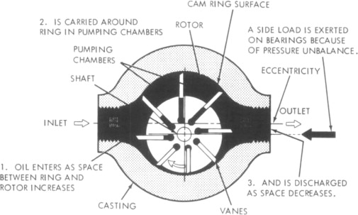
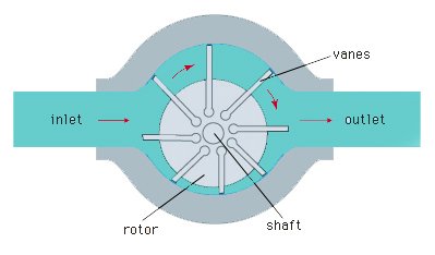
In a vane pump, there is a pump chamber inside which there is a rotor with several vanes. As the hydraulic fluid enters the pumping chamber, these vanes push it through the chamber.
The low level of noise generated by vane pumps, their ease of maintenance, and their long life make them different from other pumps. Because of their high quality, they can withstand both low-pressure and high-pressure pressures of up to 200 bar (2900 PSI).
Piston Pumps
Piston pumps are highly reliable solutions that deliver impressive results. Pumps in this category are capable of operating at pressure levels higher than 350 bar (5000 PSI).
Through its mechanical action, a piston pump creates a vacuum at its inlet line that allows the reservoir’s liquid to be forced into the inlet line by atmospheric pressure. Mechanical action then forces this liquid into the hydraulic system via the pump’s outlet.
Piston pumps have flow regulators that can control the flow per rotation, which makes them more efficient than gear pumps.
Axial Piston Pump
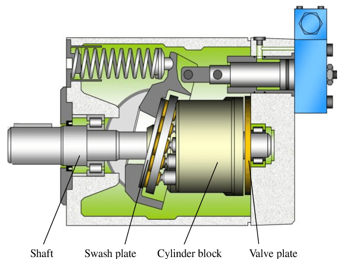
In an axial piston pump, the piston rotates parallel to the drive shaft. As a result, the revolving shaft’s movement transforms into an axial reciprocating movement. In their maximum configuration, axial piston pumps are multi-piston pumps with one-way valves or ports to pump fluid from an intake area to an outlet area.
Radial Piston Pump
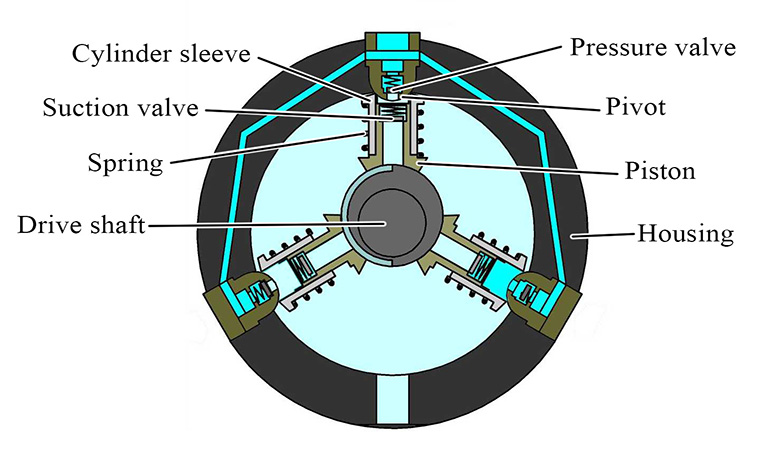
The piston in this pump is mounted radially within the cylinder block. The pistons reciprocate perpendicularly to the axis of the shaft. Depending on how the pintle or one-way valves are arranged, these can also be classified. There are variable and fixed displacements available for radial piston pumps.
Maintenance of Parts of Hydraulic Pump
Inspecting a hydraulic system regularly and performing repairs as needed will ensure that all components work in coordination.
- Consult a technician for maintenance suggestions.
- To find out if there is a problem, check the manufacturer’s instructions.
- The need for hydraulic preventive maintenance can vary with time, depending on how the equipment works. Here are some recommendations for hydraulic pump maintenance:
- Make sure the valve block is leak-free before the inspection.
- Check that the oil level in the oil tank of the power supply unit is adequate.
- Observe changes in the oil temperature.
- Check the pump for oil contamination.
- Clean the tank surfaces and other components and pipes.
- Make sure there are no leaks. Stop leakage if it exists.
- Make sure the pipe clamps and screws are tight.
- Check the pressure relief valve for smooth operation.
- Listen for changes in the motor and pump noises. This high noise may indicate a malfunction if the pump is producing louder noise than before. Get in touch with a technician to identify the problem and fix it.
Download PDF for Parts of Hydraulic Pump
In order for you to have access to this document, we included the option to download the PDF version to your computer. Click the links below to get started.
linquip.com- Parts of Gear Pump and Function Diagram Applications
Buy Equipment or Ask for a Service
By using Linquip RFQ Service, you can expect to receive quotations from various suppliers across multiple industries and regions.
Click Here to Request a Quotation From Suppliers and Service Providers
Read More on Linquip
- Top Dosing Pump Manufacturers and Suppliers in 2022
- Top Water Pump Manufacturers and Suppliers in 2022
- The 7 Best RV Water Pump In 2022 (Clear Guide + Review)
- The 10 Best Electric Air Pump in 2022 (Clear Guide)
- The Best HVAC Vacuum Pump in 2022 (Clear Guide)
- 9 Different Types of Rotary Pumps + PDF
- The 5 Best Well Pump in 2022 (Clear Guide)
- The 10 Best Condensate Pumps of 2022: A Complete Guide
- 13 Parts of Concrete Pump with Name & PDF
- 5 Types of Concrete Pumps + PDF
- 6 Parts of Pool Pump + Diagram & PDF
- 20 Parts of Submersible Pump + PDF
- 12 Parts of Sump Pump + Diagram
- 8 main Parts of Piston Pump and Function + Work & PDF
- 7 Parts of Screw Pump: Advantages and Disadvantages
- 10 Parts of Hydraulic Pump + PDF & Function
- 7 Parts of Gear Pump and Function + Diagram & Applications
- 10 Parts of Reciprocating Pumps + Function, Application and Working
- Parts of Oil Pump
- Parts of Water Pump
- Parts of Centrifugal Pumps
- Types of Fire Hydrant Systems
- Working Principles of Hydraulic Pump
- Hydraulic Pump Working Principles: Ultimate Guide
- Different Types of Hydraulic Pumps: a Complete Guide
- What is Hydraulic Pump: Learn The Basics, Boost Your Knowledge
- How Does a Hydraulic Pump Work? A Definitive Guide
- Types of Centrifugal Pumps: All Classification & Working Principles

