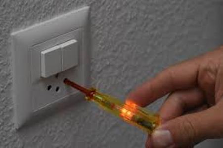
The process of the polarity test is vital in a variety of applications. Typically, when a current flow exists in a conductor, there is always a doubt whether it is a neutral or a phase. For this, an electric tester is employed to check the wire. For example, when we examine the two terminals of the batteries, one performs like a positive and the other one works as a negative terminal which is recognized as a DC supply.
However, here, the flow of current comprises only a single way which does not rotate. In the AC supply, the current direction is inverted for each cycle because the current direction is not constant here. Therefore, for any device’s operation, its terminals’ polarities must be identified for proper connections. For example, if appropriate connections are not made in a house without experiencing a polarity test, it may end in a short-circuit. So, to avoid such situations, we manage a polarity test for every device prior to its operation.
Get information about the polarity test on Linquip’s website and discover everything you need to know about it. In case you have any questions concerning polarity testing, Linquip’s experts in power transmission and distribution are available to answer them. It is advisable that you first read Linquip’s article entitled “What Is an Electrical Power Transmission?“.
We are offering you the opportunity to join Linquip as an Expert and access the full range of benefits Linquip offers. Are you interested in writing a Guest Post on Linquip? If so, you can do that by submitting your content as a guest on the Linquip platform.
What Is the Polarity Test?
It is a test carried on both the primary and secondary windings of a transformer and also to identify the direction of the current. It assists in inter-connecting the primary winding and secondary windings in the case of the transformer’s parallel operation.
Why Do a Polarity Test?
The polarity test’s importance is that by identifying the polarity of various windings, we can avoid short-circuits while operating the transformers in parallel.
To reach peak demands, the transformers are joined in parallel to perform. For the transformer’s parallel operation, the polarity of the transformer windings must be distinguished, i.e. both primary and secondary winding.
The principal winding having a positive terminal should be attached to the positive terminal of a primary winding of the other transformer. Furthermore, secondary winding having identical polarity terminals should be attached.
The primary winding has a positive terminal, joined to the negative terminal of the other transformer primary winding. Then, the short circuit of the winding takes place which destroys the entire device. This is why a polarity test is accomplished on the transformer for decent parallel operation.
What are the Polarity Testing Methods?
There are various methods for polarity test, which are described below:
Employing a Multimeter
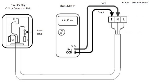
A multimeter finds the voltage at different terminals. The multimeter has two probes, including red and black. The red probe is embedded to the line and the other to the neutral if the pointer gives any deflection, we can assume it as a Line (L). If not, check by attaching the probes to the other terminals one after the other and recognize the deflection. The multimeter type method of finding the polarity is presented in the figure below.
By knowing the resistance value
One can obtain the resistance of the windings and can resolve the polarity. The Earth wire has lower resistance in comparison with the Line. Earth wire has to keep low resistance compared to the Line (L) to divert surge currents in a short-circuit case.
Types of Polarity Testing of Transformer
There are generally two types of polarity testing of transformer:
- Additive
- Subtractive
Additive Polarity
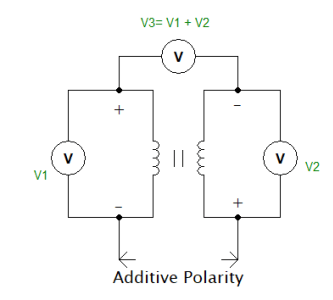
In this method, the voltmeters V1 and V2 are connected across the transformer’s primary and secondary windings. The voltmeter V1 marks the voltage across the primary winding, whereas voltmeter V2 marks the secondary winding voltage. Aside from these two voltmeters, a third voltmeter V3 is attached across both the windings, i.e., the primary winding and secondary winding. If V3 indicates voltage as the summation of both V1 and V2, it is an additive type.
The primary winding and the secondary winding polarities are varied. The terminals A1 and B2 have identical polarity, whereas A2 and B1 have similar polarity. The figure which describes the Additive type polarity is exhibited in the figure below.
Subtractive Polarity
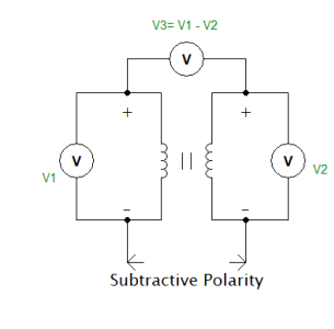
The voltmeters V1 and V2 are joined across the transformer primary and secondary windings. The voltmeter V1 marks the voltage across the primary winding, whereas voltmeter V2 marks the secondary winding voltage. Aside from these two voltmeters, a third voltmeter V3 is attached across both the windings, including a primary winding and secondary winding. If V3 reads voltage as the difference between both V1 and V2, it is a subtractive type.
The primary winding and the secondary winding polarities are identical. The terminals A1 and A2 have identical polarity, whereas B1 and B2 have the same polarity. The figure which illustrates the subtractive type polarity is displayed in the figure below.
Practical Procedure for Testing of Transformer
Equipment needed for the effective testing of the transformer is an auto-transformer, voltmeters, and a transformer.
Functionally connect the primary winding of the transformer to an auto-transformer. The effective working figure of a polarity test on the transformer is given in the figure below.
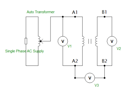
The procedure of a practical polarity test is as follows:
- Attach the first voltmeter across the primary winding and the second voltmeter across the secondary winding. The third voltmeter is then attached across the two windings.
- Gradually change the auto-transformer to its rated value, we recognize the voltmeter readings start to change.
- Remark all the readings of voltmeters. From the values of voltmeters, we can achieve whether the polarity is additive or subtractive.
- If the third voltmeter’s reading is the addition of both voltmeters, it is an additive type.
- If the third voltmeter reading is subtractive of both voltmeters, then it is a subtractive type.
The following precautions must be taken into account in a polarity test of a transformer:
- Examine the practical connections are not loose.
- Do not wire during operation.
When we look into the procedures of the distribution transformers, we discover that they require to work all the time and also demand to supply at high need at peak times. So, to cope up with these conditions, we connect the transformers in parallel.
Paralleling is made by joining the same polarity terminals of the primary winding together. A similar method is done for the secondary winding. Paralleling will enhance the power supplying capacity and also the system reliability.
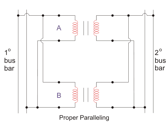
We do polarity tests on parallel transformers to guarantee that we join the same polarity windings and not the opposite ones. If we inadvertently connect the opposite polarities of the windings, it will end in a short-circuit and ultimately damage the machine.
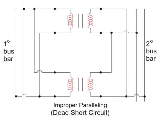
Suppose we require additive polarity but we have subtractive polarity. In this situation, we can easily change it by holding either of the primary or secondary windings in the same fashion and converting the other one’s winding connection. Similarly, if we need subtractive polarity but have additive polarity, we could do the same procedure as above.
Polarity Test of Lighting Circuit
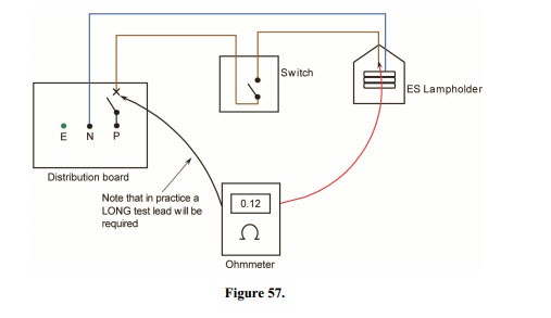
A polarity test for a lighting circuit must be made when fresh or after a change has been made. This test ensures that the phase-conductor is linked to the MCB or FUSE, and only pole switches, alternately the neutral. In the below figure, any type of Edison-Screw light holder must be tested to ensure that the phase-conductor is linked with the center contact and the neutral to the contact of the screw.
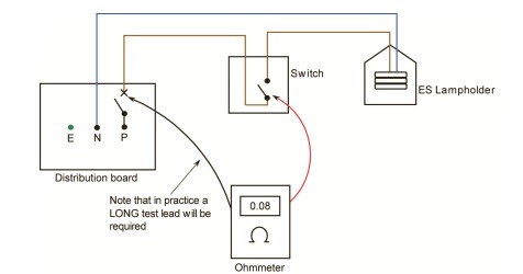
Disconnect the fuse from the circuit or discharge MCB (miniature circuit breaker). Take away all lamps from the relevant circuit. Connect one finish of the long trailing terminal to the departing terminal of the MCB circuit.
By another end, in combination with the test meter terminals, write down the readings from the phase lead at all the tips in the circuit region. For example, ES light holders stability at each end assures that polarity is correct. If the power supply is disconnected from the setting up, the long trailing terminal may be allied to the phase busbar, and the small circuit breaker must be left in the position of ‘ON’.
Polarity Test of Induction Motor
Carrying Polarity test of new three phase Induction motor is inevitable before going into operation. If the wrong polarity motor is provided with three phase supply, the magnetic field configuration within the motor windings becomes uneven, and the output torque becomes pulsating. The motor draws excessive currents, which leads to damage to the windings.
If we have a new Induction motor without any sense of the leads, we must identify its polarity before utilizing it. Ordinarily, six terminals from the three phases of an induction motor are available. If their polarity markings (A1, A2; B1, B2; C1, C2) are unknown, these can be located out by a polarity test on the induction motor.
Methods of Polarity Test of Induction Motor
There are two ways to distinguish the Polarity of three phase Induction motor:
- Discovering polarity by Using A.C supply
- Discovering Polarity by Using D.C supply
Finding Polarity of Induction Motor-Method I (by A.C)
The following equipment is required:
- Six terminal Induction motor
- Multimeter or Continuity Tester
- Single-phase A.C supply
- A.C Voltmeter
The aforementioned procedure is explained here:
Step 1: Continuity test to identify each of the winding terminals [AA BB CC]
We can do this test with the guidance of a multimeter by monitoring continuity between any two terminals. If the two terminals belong to the same winding, a beep will happen.
Do this method for all and identify terminals, then note the terminals as AA, BB, and CC.
Step 2: Test to identify polarities [A1A2 B1B2 C1C2]
Take any two windings randomly and note the terminals as A1 A2, B1 B2 (this is the assumption) as given in the figure.
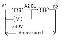
Now connect A2 to B1 so that the two windings are in series.
Now employ 230V A.C between A1 and A2 and regulate the voltage across A1 and B2.
If we notice the determined voltage is less than the employed voltage, then our assumption is right. Otherwise, interchange the terminals A1 and A2 and replicate the process to find the terminals A1, A2, B1, and B2.
Now take the third winding mark as C1, C2 (this is the assumption) and take the second winding B1B2 (already known) connect B2 to C1 so that the two windings are in series as shown in the figure below.
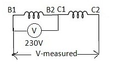
Now apply 230V A.C among B1 and B2 and determine the voltage across B1 and C2.
If we notice that the determined voltage is less than the applied voltage, then our assumption is right. Otherwise, interchange the terminals C1 and C2 and replicate the process to find the terminals B1, B2, C1, and C2.
Once we can recognize all the terminals, they are joined for Star or Delta fashion; for star connection, join A2B2C2 or A1B1C1; for delta connection, connect A2B1, B2C1, and A1C2.
Finding Polarity of Induction Motor-Method II (by D.C)
The following equipment is required:
- Center – zero galvanometer or milli voltmeter or milli ammeter
- Switch and wires
- Battery (1.5V or 3V)
Procedure to identify terminals A1, A2 and B1, B2
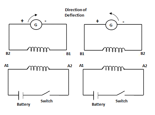
- Randomly pick one of the phase winding terminals, say A1 and A2.
- Attach the positive terminal of the battery to A1 and the negative terminal to A2 through a switch.
- The meter is attached across one of the other two-phase windings, say B phase randomly.
- At the moment of closing the switch, recognize the deflection of the meter pointer.
- If there is a positive or clockwise deflection, then the terminal attached to the positive meter is B2, and connected to the negative terminal is B1.
- If the deflection is in the reverse direction, then the polarities are B1 and B2, respectively.
Procedure to identify other terminals C1, C2
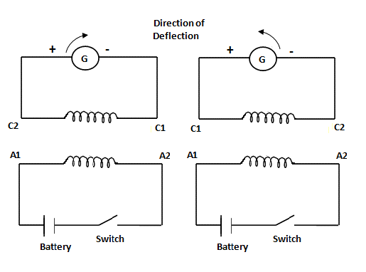
- Pick the first winding with terminals, say A1 and A2.
- Attach the positive terminal of the battery to A1 and the negative terminal to A2 through a switch.
- The meter is joined across the third phase winding.
- At the moment of closing the switch, recognize the deflection of the meter pointer.
- If there is a positive or clockwise deflection, then the terminal attached to the positive meter is C2, and connected to the negative terminal is C1.
- If the deflection is in the reverse direction, then the polarities are C1 and C2, respectively.
Download Polarity Test PDF
If you would like to access a PDF version of this article, please click on the download link below.
Buy Equipment or Ask for a Service
By using Linquip RFQ Service, you can expect to receive quotations from various suppliers across multiple industries and regions.
Click Here to Request a Quotation From Suppliers and Service Providers
Read More In Linquip
- Solid vs Stranded Wire (A Practical Guide)
- What is a Fuse Wire & How Does It Work?
- Types of Electrical Wire + Application (Complete Guide)
- 3 Common Types of Electrical Connectors (Clear Guide)
- Types of Sensors Detectors/Transducers: An Entire Guide
- 15 Types of Electrical Power Connectors (Clear Guide) + PDF
- The 8 Best Circuit Breaker Locators in 2022
- The 10 Best Mini/Benchtop Milling Machine in 2022
- 10 Best CNC Machines & Routers for WoodWorking in 2022
- The 8 Best Rust Converter in 2022 (Review Guide)
- The Best USA Thermocouple Manufacturers in 2022

