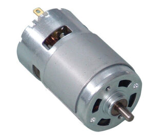
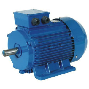
We all have heard of electric motors, but a question would always come to mind: “What is the Principle of Electric Motor”? The electric motor is a device which converts electrical energy to mechanical energy. There are mainly three types of electric motor.
- DC Motor.
- Induction Motor.
- Synchronous Motor.
All of these motors work with more or less the same principle. Working of electric motor mainly depends upon the interaction of magnetic field with current.
What is the Principle of Electric Motor: Moving the Motor by Electromagnetism
The basic idea of an electric motor is really simple: you put electricity into it at one end and an axle (metal rod) rotates at the other end giving you the power to drive a machine of some kind. How does this work in practice? Exactly how do your convert electricity to movement? To find the answer to that, we have to go back in time almost 200 years.
Suppose you take a length of ordinary wire, make it into a big loop, and lay it between the poles of a powerful, permanent horseshoe magnet. Now if you connect the two ends of the wire to a battery, the wire will jump up briefly. It’s amazing when you see this for the first time. It’s just like magic! But there’s a perfectly scientific explanation.
When an electric current starts to creep along a wire, it creates a magnetic field all around it. If you place the wire near a permanent magnet, this temporary magnetic field interacts with the permanent magnet’s field. You’ll know that two magnets placed near one another either attract or repel. In the same way, the temporary magnetism around the wire attracts or repels the permanent magnetism from the magnet, and that’s what causes the wire to jump.
What is the Principle of Electric Motor: Fleming’s Left-Hand Rule
You can figure out the direction in which the wire will jump using a handy mnemonic (memory aid) called Fleming’s Left-Hand Rule (sometimes called the Motor Rule).
Hold out the thumb, first finger, and second finger of your left hand so all three are at right angles. If you point the seCond finger in the direction of the Current (which flows from the positive to the negative terminal of the battery), and the First finger in the direction of the Field (which flows from the North to the South pole of the magnet), your thuMb will show the direction in which the wire Moves.
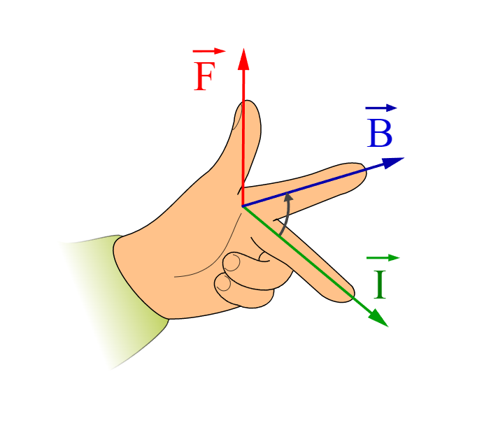
That’s…
- First finger = Field
- SeCond finger = Current
- ThuMb = Motion
What is the Principle of Electric Motor: How an Electric Motor Works
In theory, suppose we bend our wire into a squarish, U-shaped loop so there are effectively two parallel wires running through the magnetic field. One of them takes the electric current away from us through the wire and the other one brings the current back again. Because the current flows in opposite directions in the wires, Fleming’s Left-Hand Rule tells us the two wires will move in opposite directions. In other words, when we switch on the electricity, one of the wires will move upward and the other will move downward.
If the coil of wire could carry on moving like this, it would rotate continuously—and we’d be well on the way to making an electric motor. But that can’t happen with our present setup: the wires will quickly tangle up. Not only that, but if the coil could rotate far enough, something else would happen.
Once the coil reaches the vertical position, it flips over, so the electric current flows through it the opposite way. Now the forces on each side of the coil reverses. Instead of rotating continuously in the same direction, it moves back in the direction it just come from! Imagine an electric train with a motor like this: it keeps shuffling back and forth on the spot without ever actually going anywhere.
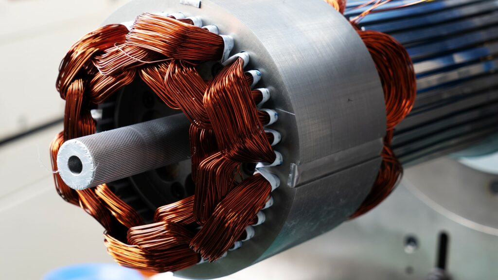
In practice, there are two ways to overcome this problem. One is to use a kind of electric current that periodically reverses direction, which is known as an alternating current (AC). In the kind of small, battery-powered motors we use around the home, a better solution is to add a component called a commutator to the ends of the coil.
Don’t worry about the meaningless technical name: this slightly old-fashioned word “commutation” is a bit like the word “commute”. It simply means to change back and forth in the same way that commute means to travel back and forth. In its simplest form, the commutator is a metal ring divided into two separate halves and its job is to reverse the electric current in the coil each time the coil rotates through half a turn. One end of the coil is attached to each half of the commutator.
The electric current from the battery connects to the motor’s electric terminals. These feed electric power into the commutator through a pair of loose connectors called brushes, made either from pieces of graphite (soft carbon similar to pencil “lead”) or thin lengths of springy metal, which (as the name suggests) “brush” against the commutator. With the commutator in place, when electricity flows through the circuit, the coil will rotate continually in the same direction.
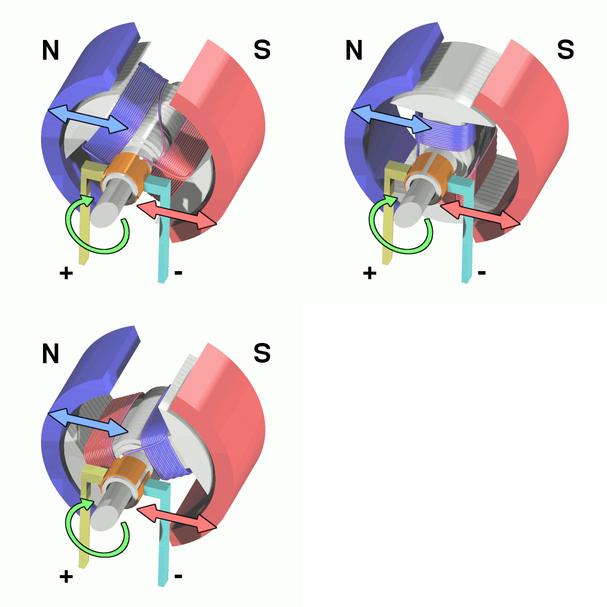
A simple, experimental motor such as this, is not capable of making much power. We can increase the turning force (or torque) that the motor can create in three ways: either we can have a more powerful permanent magnet, or we can increase the electric current flowing through the wire, or we can make the coil so it has many “turns” (loops) of very thin wire instead of one “turn” of thick wire.
In practice, a motor also has the permanent magnet curved in a circular shape so it almost touches the coil of wire that rotates inside it. The closer together the magnet and the coil, the greater the force the motor can produce.
Although we’ve described a number of different parts, you can think of a motor as having just two essential components:
- There’s a permanent magnet (or magnets) around the edge of the motor case that remains static, so it’s called the stator of a motor.
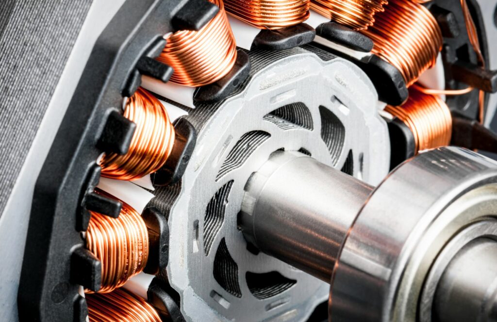
- Inside the stator, there’s the coil, mounted on an axle that spins around at high speed—and this is called the rotor. The rotor also includes the commutator.
You can watch here to get a more illustrative sense about the working principle of electric motors.
What is the Principle of Electric Motor: Working of DC Motors
Working principle of DC Motor mainly depends upon Fleming Left Hand rule. In a basic DC motor, an armature is placed in between magnetic poles. If the armature winding is supplied by an external DC source, current starts flowing through the armature conductors. As the conductors are carrying current inside a magnetic field, they will experience a force which tends to rotate the armature.
Suppose armature conductors under N poles of the field magnet, are carrying current downwards (crosses) and those under S poles are carrying current upwards (dots). By applying Fleming’s Left-hand Rule, the direction of force F, experienced by the conductor under N poles and the force experienced by the conductors under S-poles can be determined. It is found that at any instant the forces experienced by the conductors are in such a direction that they tend to rotate the armature.
Again, due this rotation the conductors under N-poles come under S-pole and the conductors under S-poles come under N-pole. While the conductors go form N-poles to S-pole and S-poles to N-pole, the direction of current through them, is reversed by means of commutator.
Due to this reversal of current, all the conductors come under N-poles carry current in downward direction and all the conductors come under S-poles carry current in upward direction as shown in the figure. Hence, every conductor comes under N-pole experiences force in same direction and same is true for the conductors come under S-poles. This phenomenon helps to develop continuous and unidirectional torque.
What is the Principle of Electric Motor: Working of Induction Motors
Working of electric motor in the case of induction motor is little bit different from DC motor. In single phase induction motor, when a single-phase supply is given to the stator winding, a pulsating magnetic field is produced and in a three-phase induction motor, when three phase supply is given to three phase stator winding, a rotating magnetic field is produced.
The rotor of an induction motor is either wound type or squirrel cadge type. Whatever may be the type of rotor, the conductors on it are shorted at end to form closed loop. Due to rotating magnetic field, the flux passes through the air gap between rotor and stator, sweeps past the rotor surface and so cuts the rotor conductor.
Hence according to Faraday’s law of electromagnetic induction, there would be an induced current circulating in the closed rotor conductors. The amount of induced current is proportional to the rate of change of flux linkage with respect to time. Again, this rate of change of flux linkage is proportional to the relative speed between rotor and rotating magnetic field. As per Lenz law the rotor will try to reduce every cause of producing current in it. Hence the rotor rotates and tries to achieve the speed of rotating magnetic field to reduce the relative speed between rotor and rotating magnetic field.
What is the Principle of Electric Motor: Working of Synchronous Motors
In synchronous motor, when balanced three phase supply is given to the stationary three phase stator winding, a rotating magnetic field is produced which rotates at synchronous speed. Now if an electromagnet is placed inside this rotating magnetic field, it is magnetically locked with the rotating magnetic field and the former rotates with the rotating magnetic field at same speed that is at synchronous speed.

