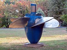
The propeller turbine is a type of inward flow reaction turbine with a propeller-shaped runner, which can be seen in ships and submarines. It is equipped with either fixed or adjustable blades. In the propeller turbine, the water flow is regulated by adjustable guide vanes (or wicket gates). The vanes move the water into the runner to transfer its energy to the blades. The propeller turbine is usually employed in hydraulic sites with high flow rates.
There is a great deal of information about hydro turbines on the Linquip website, and our goal is to make it as informative as possible. We hope the data you find here will be useful to you. Linquip is one of your best options if you have questions or concerns about turbines. In case you have any questions about these types of turbines, you are welcome to contact the Linquip experts at any time. We would like to highly encourage you to spend some time reading Linquip’s article entitled, “What Is Hydro Turbine?“.
Linquip contains several components that require a Linquip Expert registration in order to fully utilize all the benefits available on the platform. A Linquip profile allows you to display your skills in a way that is based upon industrial equipment. Are you interested in writing a guest post as part of the Linquip community? Are you open to making such a contribution? There is the possibility for you to upload your content to the Linquip platform utilizing the Guest Posting section.
Different types of propeller turbines available in the hydraulic power industries are bulb turbine, Straflo turbine, tube turbine, and Kaplan turbine.
Propeller Turbine Working Principle
Most reaction turbines are propeller type. The propeller turbine runner generally has three to six blades, to which water strikes continuously at a constant rate. The blades pitch may be fixed or adjustable. The main components of a propeller turbine are the runner, a scroll case, wicket gates, and the draft tube.
The main part of the runner is the propeller including the rotating hub and blades to carry the fluid potential and kinetic energy to the shaft attached to the turbine. Propellers can be classified based on different methods, such as the number of blades or blade pitch. You can visit this link to learn more about the propeller.
The flow direction is axial for most propeller turbines, parallel to the axis of rotation. They are therefore categorized as mid-flow turbines.
Early developments used propeller turbine units with vertical shafts. More recent developments utilize a horizontal shaft. The blade of a propeller turbine can be rigidly attached to the hub, called fured-blade runners. The runner blades can also be built adjustable so that the turbine can work more efficiently in a wide range of flow conditions.
A propeller turbine with adjustable blades and gates is a Kaplan turbine in honor of its inventor, Viktor Kaplan. A propeller-type turbine that has adjustable blades and fixed gates is sometimes called a semi-Kaplan. The automatic coordination of runner blades movement and adjusting the wicket gates position causes optimum hydraulic performance, making such units more efficient for variable flow rates and low head applications.
Propeller turbines are designed for heads from 1.5 to 60 meters but are usually used for heads less than 30 meters. In a fixed blade propeller turbine, the range of flow operation is better to be between 75 and 100% of best efficiency point (BEP) flow. Kaplan turbines may operate between 25 and 125% of the best efficiency discharge rate. The head range for the adequate performance of the turbine is from 20 to 140% of the design head.
Propeller Turbine Types
Although the most well-known type of propeller turbine is the Kaplan turbine, there are other types of propeller turbines that we will explain in this section.
Bulb Turbine
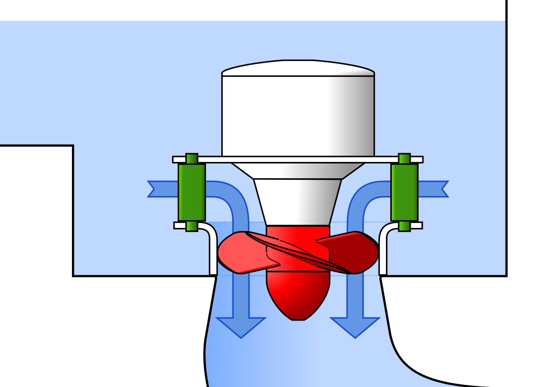
In the bulb turbine, the turbine and generator are sealed and installed directly in the water flow. Bulb turbine is proper for low heads, less than 25 meters. The almost straight design of the water flow reduces both the size and costs. A bulb turbine is a compact unit with an upstream watertight casing containing a generator mounted on a horizontal axis. The advantage of these turbines is that they take up little space due to the sealed turbine and generator. However, this feature makes it difficult to access turbine components for service.
Bulb turbines are also able to work in reverse flow directions. For very low heads, an additional set of gears is utilized to increase the rotational speed of the generator. However, both the set-up gears and the generator are put in an open pit rather than a bulb. Bulb turbines are available to generate power in the range of 10 to 100 MW.
A schematic diagram of a bulb turbine, including turbine blades (in red), distributers (in green), generator (in the white bulb), bulb casing (around the white bulb), and water flow is shown in the following figure.
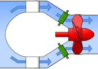
The generator is designed in such a way that all mechanisms are compressed to a diameter nearly equal to the propeller diameter. The variable-pitch propeller located at the downstream end of the bulb drives the generator. The very compact nature creates some advantages in the design of the power plant and water flow pattern. It requires appropriate cooling and air circulation inside the generator bulb.
Straflo Turbine
An American L. F. Harza developed rim-generator turbines. The first units were built by European companies during World War II. The name Straflo has been chosen as the exclusive name by Escher Wyss, the company that makes these rim-generator units. Straflo is a registered trademark abbreviation of straight flow.
One of the main features of the Straflo turbine is the combination of turbine and generator, which leads to less required space. A Straflo turbine also includes a group of axial turbines with a generator arranged concentrically outside the flow channel.
The following figure shows the water flow passing the main components of a Straflo turbine.
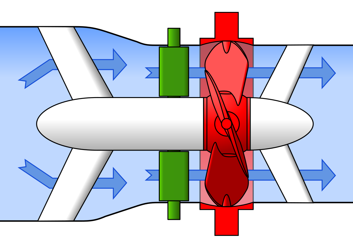
The generator is connected to the propeller runner periphery, and the stator is installed inside the civil works surrounding the water channel. Only one crane is needed for maintenance, thus decreasing space requirements and complexity of construction works. The rotor relatively larger diameter creates greater unit inertia than that of bulb generators, which is an advantage in operating stability.
Tube Turbine
In a tube turbine, the penstock curves right before or after the runner, which makes a straight-line connection to the generator. The output power generated by the tube turbines ranges from 20 to 700 kW. Tube turbines have a direct drive configuration in which the turbine and the generator are mounted on the same shaft with common bearings and seals.
The main features of tube turbines are listed here:
- A compact arrangement including turbine and generator with bearings and seals in a single unit
- The stainless steel construction
- Ability to install the unit vertically or horizontally
- Large service intervals
- Heads ranging from 5 to 30 meters for most applications
The tubular propeller turbine has guide vanes instead of the spiral casing. If the generator is placed inside a bulb in the water flow passage, this type of propeller turbine is sometimes referred to as a bulb turbine. Three tubular propeller turbine configurations are vertical shaft, pit, and S-type. They are appropriate for heads of 5 meters or less with a syphon type arrangement.
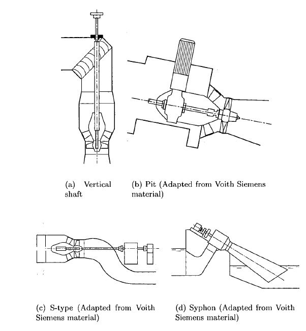
Pit turbines can be classified as bulb turbines with a gearbox. This structure makes it possible to have a small generator and bulb.
S-type turbines omit the requirement for bulb housing by installing the generator outside the water channel. This is performed with a jog in the channel and a shaft connecting the generator and the runner.
Kaplan Turbine
In a Kaplan turbine, the blades and the wicket gates are adjustable, which makes the Kaplan a flexible turbine for a wider range of operation. In this type of propeller turbine, the rotor is connected to the turbine shaft and spins at a fixed rotational speed. When the rotor rotates, it causes the electromagnetic field poles to pass by the conductors placed in the stator. This, in turn, generates an electric current and creates voltage to develop at the output terminals of the generator. To know more about this process, you can read this article.
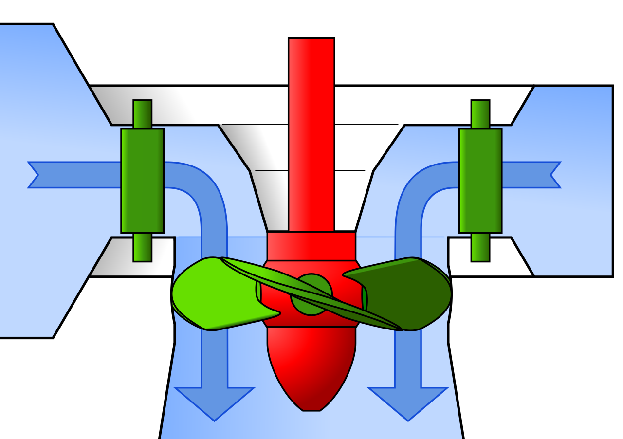
The rotational velocity of the generator is usually equal to that of the turbine since they are directly connected. However, some power plant designs use a gearbox between the turbine and the generator to increase the speed. The geometric design and hydraulic conditions determine the rotation speed of the turbine. Kaplan generators speeds are generally in the range of 50 to 600 rpm. For a generator running in a 60 Hz system, the rotational speed (rpm) times the number of poles of the field on the rotor is always equal to 7200.
The structure of the stator is like a donut that surrounds the rotor. The stator consists of a steel frame that supports the stacked steel laminations. The conductors (also called stator winding) are recessed in slots in the lamination construction. The stator winding is organized so that when the rotor spins, the poles of the field pass only a portion of an inch from it. The movement of the magnet adjacent to the conductor causes an electric current in the conductor.
Larger generator stator windings consist of individual stator coils. Each coil includes multiple strands of copper insulated with mica kept in place with epoxy or a polyester resin. Individual coils are attached by jumpers and then to a ring bus which is connected to the generator leads. The generator leads, in turn, are connected to the power step-up transformer. Subsequently, the transformer is attached to the electrical power grid.
The following figure compares the operating range of Kaplan with some other famous hydro turbines, including Francis, Pelton, and Turgo.
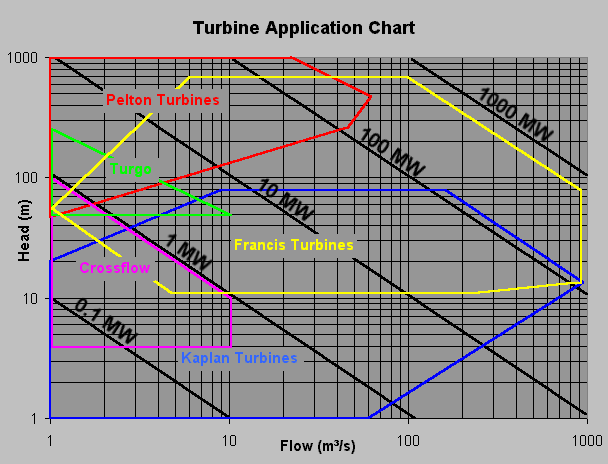
The Kaplan turbine is an evolved form of the Francis turbine. Its development allowed efficient power generation in low-head sites, which was not reasonable with Francis turbines. The head ranges between 10 and 70 meters, and the output power ranges between 5 and 200 MW. The diameters of the runners are from 2 to 11 meters. Turbines rotate at a constant speed, varying from unit to unit. The rotational speed may range from 54.5 rpm to 450 rpm.
Today, Kaplan turbines are widely used worldwide in cases with high flow rates and low heads.
VLH Turbine
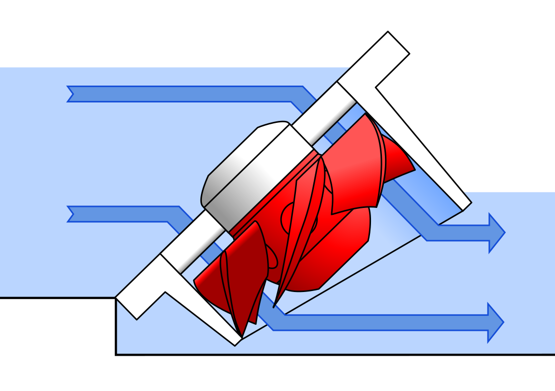
The VLH (Very low Head) turbine is an open channel flow, a Kaplan turbine inclined at an angle (typically 45 degrees) to the water flow. The VLH turbine diameter is large than standard Kaplan (more than 3.55 meters). It has low rotational speed using a directly connected shaft located permanent magnet alternator with electronic power regulation system. One of the most important benefits of VLH is the fish friendliness of the turbine, which leads to a mortality rate lower than 5%.
DIVE Turbine
The DIVE Turbine is a vertical propeller turbine regulated by both wicket gates and speed variation. It is suitable for a range of power generation up to 4 MW. The efficiency of the DIVE turbine is comparable to standard Kaplan turbines. This turbine is considered a fish-friendly turbine as a result of the propeller design with fixed blades.
Tyson Turbine
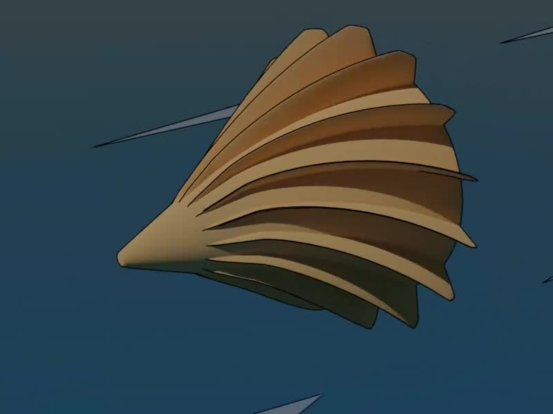
Tyson turbine is a fixed propeller turbine with helical blades for the application of being immersed in a fast-flowing river. It can be permanently anchored in the river bed or connected to a boat or barge.
Propeller Turbine Advantages and Disadvantages
As mentioned in detail, different types of propeller turbines have been developed for various purposes. However, they do share some strengths and weaknesses, some of which are explained here.
Advantages
- Impeller turbines are usually used for applications in small heads that are is not reasonable for other counterparts such as Francis.
- Impeller turbines with adjustable blades or guide veins can have optimal hydraulic efficiency to suit flow conditions.
- Compactness is one of the advantages of groups of impeller turbines such as bulb turbines.
- They require construction with lower costs and less space.
Disadvantages
- Sealing the generator and rotor in samples such as bubbles and Straflo can make it difficult to access various components for maintenance.
- Cavitation and its consequences are some of the dangers that propeller turbines are exposed to.
- The possibility of water leaking into the generator housing can cause damage to the hydroelectric system.
- Propeller turbines usually require a large volume of water flow to operate.
Download Propeller Turbine PDF
For your convenience, you can access the whole contents of this article by clicking on the following link, which contains the entire article in a PDF format.
Read More In Linquip
- Impulse Turbine: Working Principle, Components, and Types
- An Ultimate Guide to Francis Turbine
- Cross-Flow Turbine: Working Principle, Components, and Advantages
- Types of Propellers, Historical Development, and The Ways of Their Construction
- What is Mixed Flow Turbine? Basics, Advantages, and Applications
- What is Low Head Turbines?
- What are Floating Wind Turbines? A Practical Guide to Advantages and Types
- What is Tesla Turbine and How Does it Works?
- What is Hydrokinetic Turbines? Working Principles and Output Power
- What is Turgo Turbine and How does it Work?
- What is Kaplan Turbine? Diagram and Working Principles
- What is Wind Turbine? The Short and Essential Answer

