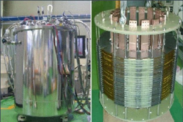
Superconducting magnetic energy storage (SMES) systems deposit energy in the magnetic field produced by the direct current flow in a superconducting coil, which has been cryogenically cooled to a temperature beneath its superconducting critical temperature.
What Are Superconducting Magnetic Energy Storage Devices?
SMES was originally intended for large-scale load leveling, but due to its rapid-discharge capabilities, it has been deployed on electric power systems for pulsed-power and system-stability applications.
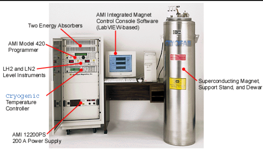
Superconducting Magnetic Energy Storage is a new technology that stores power from the grid in the magnetic field of a superconducting wire coil with a near-zero energy loss.
The device’s major components are stationary, making it extremely stable. Furthermore, the uncertainty associated with power generation from various renewable energy sources, such as solar and wind, is projected to bring up new potential prospects in this industry.
SMES is a grid-enabled device that can store and discharge enormous amounts of energy almost instantly. To replace a rapid loss or dip in line power, the system may release high quantities of power in a fraction of a cycle. With today’s crowded power lines and the increasing penetration of renewable energy sources such as wind and solar, the intentional injection of brief bursts of electricity can play a crucial role in guaranteeing grid resilience.
A typical SMES consists of two stationary pieces – a cryogenically cooled superconducting coil and a power conditioning system – that provide more reliability than many other power storage technologies. The current should not decay once the superconducting coil is charged, and the magnetic energy should be kept indefinitely.
How Can Superconductors Be Used to Store Energy?
An electric current is routed through a coil formed of superconducting wire to store the energy. Because there is no loss, after the coil is short-circuited (closed), the current stays constant and produces a magnetic field, similar to MRI coils. As a result, the energy is stored in the coil in both magnetic and electric forms, and it may be recovered in a relatively short period.
Ferrier invented the use of superconducting coils to store magnetic energy in 1970. The coil must be superconducting; otherwise, the energy is wasted in a few milliseconds due to the Joule effect. The SMES has a high power density but a moderate energy density, a large (infinite) number of charge/discharge cycles, and a high energy conversion productivity of over 95%.
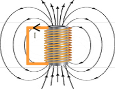
A SMES system is more of an impulsive current source than a storage device for energy. As a result, SMES is a great choice for non-interruptible power supply systems (NIPSS) or some FACTS (Flexible AC Transmission System), which are static equipment used to improve electric networks.
Another potential for SMES includes the requirement for impulsive energy sources for new applications such as electromagnetic throwers for military and civilian use. SMES is a very practical solution that offers numerous advantages over traditional methods in terms of efficiency, lightweight, and congestion.
Several SMES systems have demonstrated their performance and operating capabilities for megawatts of power and durations of less than a second. They’ve been employed to stabilize electric networks or as interruptible sources (or “undulators”) for sensitive charges.
In the 1980s, SMES was also the first superconducting application utilized on a BPA (Bonneville Power Administration) electric network. These systems are available for purchase in stores, and previous experience in the United States and Japan has been quite positive. However, due to the tremendous initial cost and competition from more advanced technology, only a few SMES systems have been sold. Even though high-temperature materials cannot reduce the overall cost, they improve the mass performance of superconducting magnets and lower the cost of cryogenics, making SMES systems more appealing (investment and functioning).
Working Principle of Superconducting Magnetic Energy Storage
Any loop of wire that produces a changing magnetic field in time also creates an electric field, according to Faraday’s law of induction. The electromotive force extracts energy from the wire in this operation (EMF). When going one round of a conductive loop, EMF is defined as the electromagnetic work done on a unit charge. The energy was now viewed as being stored in the electric field. This process makes use of the energy in the wire, which is equal to the electric potential multiplied by the entire charge divided by time, where Ɛ is the voltage or EMF. We may determine the work required to make such an electric field by defining the power. This amount of work must also be equal to the energy stored in the field due to energy conservation.
P=Q\epsilon /t
The substitution can be used to rewrite this calculation in the easier to measure variable of electric current.
P=Q\epsilon /t=I\epsilon
where I is the electric current (Ampere), and the EMF Ɛ is an inductance and can thus be written as:
\epsilon =L{\frac {dI}{dt}}
The substitution then gives:
P=IL{\frac {dI}{dt}}
Where L is a linearity constant referred to as the inductance in Henry. Now that the power has been determined, all that remains is to complete the work equation to determine the work.
W=\int _{0}^{T}Pdt=\int _{0}^{I}IL{\frac {dI}{dt}}dt=\int _{0}^{I}ILdI={\frac {LI^{2}}{2}}
As previously stated, the work must equal the energy stored in the field. A single looped wire serves as the basis for the entire calculation. Induction L grows as wires are looped several times because L is simply defined as the ratio of voltage to the current rate of change. In conclusion, the coil’s stored energy is equivalent to:
E={\frac {LI^{2}}{2}}
Where E is the energy measured in joules, L is the inductance measured in Henries, and I is the current measured in amperes.
Now let’s suppose a cylindrical coil with conductors of a rectangular cross-section. The mean radius of coil is R. Also, a and b are the width and depth of the conductor. f is designated form function, which is distinctive for different shapes of the coil. ξ (xi) and δ (delta) are two parameters to describe the dimensions of the coil. We can hence write the magnetic energy deposited in such a cylindrical coil as explained following. This energy is a function of coil dimensions, carrying current, and number of turns.
E=RN^{2}I^{2}f(\xi ,\delta )/2
Where E is energy measured in joules, I is current measured in amperes, f(ξ,δ) = form function, joules per ampere-meter, and N is number of turns of coil.
Advantages Over Other Energy Storage Methods
There are various advantages of adopting superconducting magnetic energy storage over other types of energy storage. The most significant benefit of SMES is the minimal time delay between charge and discharge. Power is practically instantly available, and very high power output can be delivered for a short time. The energy conversion of the stored mechanical energy back into electricity in other energy storage systems, such as pumped hydro or compressed air, takes a long time.
SMES is thus a viable alternative if demand is immediate. Another advantage is that electric currents face nearly little resistance, resulting in less power loss than other storing systems. Furthermore, the major components of a SMES are stationary, resulting in great reliability.
The benefits can be summarized as the following:
- Improves power quality for important loads and offers carryover energy during power outages and voltage drops.
- Load leveling among renewable energy sources (wind, solar) and the transmission and distribution network is improved.
- When opposed to batteries, superconductivity is better for the environment because it does not require a chemical reaction and produces no contaminants.
- SMES has a high dynamic range, practically unlimited cycle capabilities, and a near-100 percent energy recovery rate, which improves transmission line capacity and performance.
- Long-term storage SMES systems in a compact device are possible thanks to ultra-high field operation, which saves money on material and system costs.
Applications of Superconducting Magnetic Energy Storage
SMES are important systems to add to modern energy grids and green energy efforts because of their energy density, efficiency, and high discharge rate. The three main applications of the SMES system are control systems, power supply systems, and emergency/contingency systems.
FACTS
FACTS (flexible AC transmission system) devices are stationary devices that can be used in power networks. These devices are used to improve an electric power grid’s controllability and power transfer capability. The use of SMES in FACTS devices was the first time SMES systems were used. The Bonneville Power Authority was the first to implement SMES using FACTS devices in 1980. This system makes use of SMES devices to dampen low frequencies, which helps to stabilize the electrical grid. To improve the grid’s stability, SMES-based FACTS systems were installed at key points in the northern Winston power grid in 2000.
Load Leveling
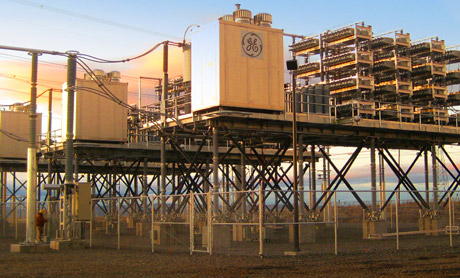
The utilization of electric power necessitates a reliable and consistent energy source. This stability is determined by the amount of power consumed and generated. The amount of energy used fluctuates during the day and throughout the seasons. When the generated power is greater than the demand/load, SMES systems can store energy and release it when the load is greater than the generated power. As a result, power fluctuations are compensated for.
By employing these methods, conventional generating units can function at a constant output, which is more efficient and convenient. The SMES, on the other hand, may be entirely discharged if the power imbalance between supply and demand persists for a long time.
Uninterruptable Power Supplies
Uninterruptible Power Supplies (UPS) provide a continuous power source to defend against power spikes and deficits. This compensation is accomplished by switching from the failing power source to a SMES system, which can nearly instantly deliver the required power to keep critical systems running. SMES-based UPSs are particularly beneficial in systems that must maintain certain critical loads.
Load Frequency Control
When the load does not match the generated power output due to a load perturbation, the load can become larger than the generators’ rated power output. This can happen when wind generators stop spinning owing to a sudden absence of wind, for example. This load disturbance may result in a load frequency control issue. In DFIG-based wind power turbines, this problem might be magnified. When the generation exceeds the load, power output from SMES systems that store energy can compensate for the load mismatch. When compared to modern control systems, SMES-based load frequency control systems have a faster response time.
Spinning Reserve
Spinning reserve refers to the additional producing capacity made available by boosting the power generation of grid-connected equipment. This capacity is set aside by the system operator to compensate for power grid outages. SMES systems can be used as a spinning reserve when a significant grid of transmission lines is out of service due to their quick recharge times and fast alternating current to direct current conversion process.
Circuit Breaker Reclosing
Protective relays prevent circuit breakers from reclosing when the power angle difference across them is too large. In these cases, SMES systems can be employed to lessen the power angle difference across the circuit breaker. As a result, the circuit breaker can be re-closed. After large transmission line outages, these systems enable for rapid restoration of system power.
SFCL
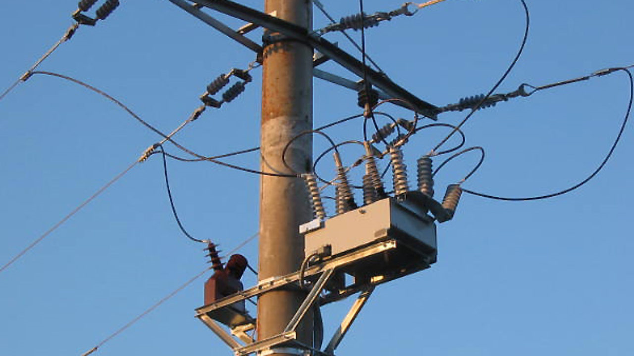
SFCLs (Superconducting Failure Current Limiters) are used to limit current in the grid when there is a fault. When a fault in the gridline is discovered in this system, a superconductor is quenched (heated). The resistance of the superconductor rises as it is quenched, and the current is directed to other grid lines. This is accomplished without interfering with the broader grid. The SFCL temperature is decreased and becomes invisible to the broader grid once the fault is cleared.
Electromagnetic Launchers
Electromagnetic launchers are electric projectile weapons that accelerate projectiles to extremely high speeds using a magnetic field. To function, these rockets require high-power pulse sources. The SMES system’s quick release capability and high power density can be used to create these launchers.
Future Developments and Technical Challenges
Future Developments of Superconducting Magnetic Energy Storage
SMES systems may become more viable for other applications as component technology improves. The development of superconductors, for example. Superconductors with higher critical temperatures are always sought by condensed matter scientists. A team of researchers even discovered a superconductor that functions at ambient temperature in 2013. This was stable for picoseconds, making it useless but demonstrating that superconductivity at ambient temperature is conceivable. The cost of refrigeration is an expense. The SMES system would be more practical and efficient if that cost could be eliminated by using a room-temperature superconductor or even a near room temperature superconductor.
Technical Challenges Toward Superconducting Magnetic Energy Storage
Current SMES systems have a rather low energy content. Large-scale storage units are frequently used to increase the amount of energy stored in SMES. Cryogenics, like other superconducting applications, are required. To contain the enormous Lorentz forces generated by and on the magnet coils, a strong mechanical structure is normally necessary. The superconductor is the most expensive component of SMES, followed by the cooling system and the rest of the mechanical construction.
Size
A SMES plant would need a loop of roughly 0.5 miles to produce commercially useful storage levels of roughly 5 GWh (3.6 TJ) (600 m). This is usually depicted as a circle, though it could be more of a rounded rectangle in practice. In any situation, a large quantity of land would be required to accommodate the installation.
Mechanical Support
Large Lorentz forces are generated by the strong magnetic field operating on the coil, as well as the strong magnetic field generated by the coil on the larger structure, therefore this is required.
Infrastructure
The infrastructure necessary for an installation is the second issue. The 0.5 miles (600 m) loop of wire would have to be confined within a vacuum flask of liquid nitrogen until room-temperature superconductors are discovered. This, in turn, would necessitate stable support, which is typically achieved by burying the installation.
Manufacturing
Around SMES, there are two production difficulties. The first step is to create a bulk cable that can carry the current. The HTSC superconducting materials discovered so far are fragile ceramics, making it difficult to draw long lengths of superconducting wire using traditional methods. Layer deposit techniques, which involve depositing a thin film of material onto a stable substrate, have received a lot of attention, but they are currently only suited for small-scale electrical circuits.
Critical Magnetic Field
The superconducting state is destroyed above a particular field strength, known as the critical field. Given that the amount of the magnetic field controls the flux captured by the superconducting coil, this means that the superconducting material has a maximum charging rate.
Long Precooling Time
At the moment, cooling the coil from room temperature to operational temperature takes four months. This also means that the SMES takes the same amount of time to warm up after maintenance as it does to resume after an outage.
Critical Current
In general, power systems strive to maximize the amount of current they can manage. As a result, any losses caused by system inefficiencies are quite minor. Due to Ampere’s Law, high currents can generate magnetic fields greater than the critical field. As a result, current materials fail to carry enough current to make a commercial storage facility financially viable.
Protection
Because of the enormous amount of energy stored, special precautions must be taken to protect the coils in the event of coil failure. In the event of a coil breakdown, the quick release of energy could cause harm to the surrounding systems. Some hypothetical designs call for including a superconducting cable into the system with the purpose of energy absorption after coil failure. In order to avoid energy loss, the system must also be kept in great electric isolation.
Cost
Because other significant components impact the cost of SMES, it is difficult to say whether HTSC or LTSC systems are more cost-effective. The conductor, which consists of a superconductor and a copper stabilizer, as well as cold support, are both significant expenses. They must be evaluated based on the device’s overall efficiency and cost. Other components, such as vacuum vessel insulation, have been proven to play a minor role in the overall cost of the coil. For toroidal coils, the cost of the superconductor outweighs the total costs of conductors, construction, and refrigeration. Solenoid coils follow the same pattern.
Consider a breakdown of primary components of both HTSC and LTSC coils corresponding to three typical stored energy levels, 2, 20, and 200 MWh, to gain some perspective into costs. For all HTSC situations, the conductor cost is the most critical of the three expenses, especially at small diameters. The main explanation is the difference in current density between LTSC and HTSC materials. In the operational magnetic field, the critical current of HTSC wire is roughly 5 to 10 teslas lower than that of LTSC wire (T).
Assume that the wire costs are the same regardless of its weight. Because the (Jc) value of HTSC wire is lower than that of LTSC wire, it will take a lot more wire to get the same inductance. As a result, the cost of wire is significantly higher than that of LTSC wire. In addition, as the SMES size increases from 2 to 20 to 200 MWh, the LTSC conductor cost increases by a factor of ten. The cost of an HTSC conductor rises more slowly, although it is still the most expensive part.
With each step from 2 to 20 to 200 MWh, the building costs of either HTSC or LTSC increase consistently (by a factor of ten). However, the cost of HTSC structure is higher because the strain tolerance of HTSC (ceramics cannot take much tensile load) is lower than that of LTSC, such as Nb3Ti or Nb3Sn, which necessitates the use of more structure materials. Thus, the HTSC cost cannot be countered merely by reducing the coil size at a higher magnetic field in very large situations.
Buy Equipment or Ask for a Service
By using Linquip RFQ Service, you can expect to receive quotations from various suppliers across multiple industries and regions.
Click Here to Request a Quotation From Suppliers and Service Providers
Read More on Linquip

