What is the importance of Thermistor Resistance? A thermistor is determined by the overall value of resistance that is detected at ambient temperature (25°C). There are particular technical features for instruments that require to maintain their temperature for optimal operation. Each designer has various needs for temperature detecting; thus, it is vital to know the concept of thermistor resistance and bias current. More exploration about them helps to specify optimum thermistor state.
What is the Thermistor Resistance Definition?
Thermistors are special resistors whose main operation is to present a great, predictable, and exact modification in electrical resistance when having temperature-variation. Some of them present a reduction in electrical resistance when subjected to temperature rising (NTCs), while others exhibit an increase in the same condition (PTCs). Thermistors can operate over the temperature level of -100° to over +600° Fahrenheit. They are typically accepted as the most beneficial transducer for various applications such as temperature monitoring and control according to their very foreseeable features and considerable stability. If you want to learn the definition of thermistor resistance more theoretically, click here.

The improvement in thermistor technology was first started based on the observation of the temperature coefficient of silver sulfide by Michael Faraday in 1833. The major property of a thermistor is its greatly high temperature constant of resistance. Modern manufacturers produce devices with considerably accurate resistance versus temperature features, making them the most useable instrument for a wide variety of applications.
A thermistor’s variation in electrical resistance according to a particular temperature change is sensible whether the thermistor’s temperature is modified as a result of radiation or conduction from the atmosphere or based on the “self-heating” due to the power dissipation through the instrument.
When a thermistor is employed in a system where the power dissipated in it is not enough to produce self-heating, the thermistor’s temperature will follow the environmental conditions. Thermistors are not self-heated to utilize in applications like temperature sensing, monitoring, or compensation.
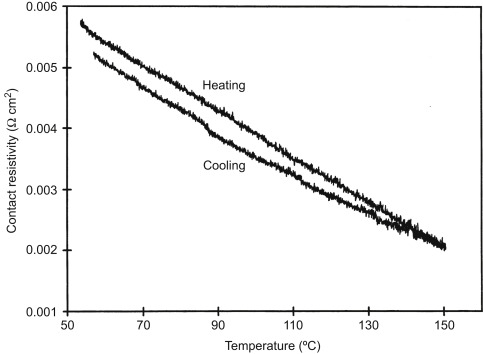
On the other hand, when the thermistor is utilized in a device where the power dissipated is great to cause self-heating, its temperature will be determined by the thermal conductivity of its surroundings. They are self-heated to use in the application, including airflow sensing, liquid level monitoring, and thermal conductivity detection.
A thermistor presents the optimum useful level based on bias current from controllers, which means that the temperature state in which few temperature variations can be precisely recorded. It is appropriate to select thermistors, including a middle set point temperature of the state you require, because the sensitivity of them is based on the temperature. For instance, thermistors are more sensitive at a cooler temperature than the higher ones.
Designers determine the upper and lower voltage limitations of the temperature transducer input by a controller. You should choose instruments and bias current configurations that generate high voltage of the range that is permitted by that controller.
Voltage is introduced as the relation to its resistance by Ohm’s law. This formula is employed because it will determine the bias current value. Ohm’s law accurately provides that currents in the conductor and are directly in relation to the actual differences across the system.
How does the Thermistor Sense Temperature?
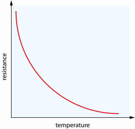
A thermistor does not practically read any value, while the thermistor resistance varies with temperature. The amount of the resistance variation is based on the substance applied in the device. Thermistors are fundamentally nonlinear, unlike other sensors. It means that just the points on a diagram present the relationship between resistance and temperature, while they do not show a straight line. The position of the diagram and how much it varies is specified by the production of the thermistor.
Thermistor Specifications
These following features are the main specification for choosing a thermistor, which can be found in the constructors’ datasheet:
- Resistance
This is the thermistor resistance at a special temperature determined by the designer.
- Tolerance
The tolerance presents how much the resistance can differ from the particular value.
- B constant
B constant is a value that provides the relationship between the thermistor resistance and temperature.
- Operating Temperature Range
Maximum and minimum temperature of the operating level.
The constructors’ datasheet contains a list of thermistor resistance ranges and particular temperatures around these ranges. One method for using this non-linear instrument is to utilize a look-up table, including the temperature-resistance information. After evaluating the thermistor resistance (which is explained later completely), you can search the table for the special temperature.
Linearizing Thermistor Response
You can calculate the thermistor response by putting a special resistor in parallel or series condition with it. However, this improvement requires extra accuracy. The amount of the resistor must be equal to the thermistor resistance at the particular reference of the temperature limit.
Thermistor – Parallel Resistor Combination
The S-shaped of the temperature-resistance diagram generated by joining a 10k resistor in the parallel form with a 10k thermistor resistance is presented at 25°C.
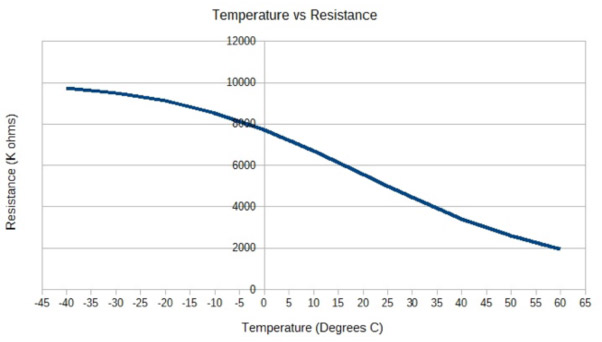
This makes the situation of the diagram between 0°C and 50°C approximately linear. The maximum linearity is close to 25°C.
Thermistor – Series Resistor Combination (Voltage Divider)
A usual method for microcontrollers to obtain analog data is using an Analog to Digital Converter (ADC). You can’t actually detect the thermistor’s resistance with an ADC. The series form of combination is demonstrated below, and it presents a simple way for voltage dividing.
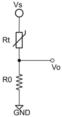
Using the next formula is for calculating the output voltage of the voltage divider system:
{ V }_{ O }={ V }_{ S }*({ R }_{ O }/({ R }_{ t }+{ R }_{ O }))
What is the Difference between A Thermistor Resistance and Other Sensors?
There are some important differences between a thermistor resistance and several other temperature sensors that are utilized in systems. The most usual types of them are RTDs and integrated circuits (IC) like the LM335 instrument. Which transducer operates perfectly for a special usage is dependent on various features. The characteristics below show a brief comparison of the advantages and disadvantages of each kind.
- Temperature Range
The approximate total range of thermistors is more suitable within 50°C of a given middle range in which the device can be employed.
- Relative Cost
The relative cost of thermistors is inexpensive in comparison with RTDs, mainly due to the material used for RTDs like platinum.
- Time Constant
The time constant of thermistors is between 6 to 14 seconds, which is the time needed to vary from one temperature value to another. This is the main drawback of using thermistors because it is too long in high-tech applications.
- Stability
Thermistors are very stable, near 0.0009°C, to maintain constant sensing according to the circuit’s temperature feedback.
Measurement Error and ADC Resolution of Thermistors
Different factors can cause measurement errors. For instance, the thermistor and its series resistors’ format may change from their fixed values, or there can be particular errors according to the self-heating effect of a noisy electrical atmosphere that can fluctuate the input of the ADC. There are a few steps to decrease the measurement error. But you should consider the B parameter formula discussed below.
1- Measuring the series resistor (R) to obtain the practical resistance and utilizing that value in the temperature control.
2- Measuring the reference resistance (R0) for the system at T0 and employ that value in final evaluations. An accurate thermometer is required to obtain precise resistance in this step. However, we can choose a thermistor and a particular resistor with more exact tolerances to decrease the error for the application.
3- The value of the B constant is based on temperature and, as explained before, is normally presented for a particular temperature level. If you can obtain precise thermistor resistance values at two different temperatures, especially at the endpoints, you can employ the next equation to find the practical constant of your thermistor.
B=\ln { ({ R }_{ 1 }/{ R }_{ 2 }) } *({ t }_{ 1 }*{ t }_{ 2 })/({ t }_{ 2 }-{ t }_{ 1 })
It is essential to maintain the power dissipation as little as possible to prevent the self-heating effect. Also, using some desirable ADC readings in the temperature monitoring and a reference voltage source for Vref is necessary for the system.
How does A Thermistor Resistance Work in a Controlled System?
The main advantage of a thermistor is to sense the temperature of any device. The thermistor is a small but essential instrument of a larger circuit in a temperature-controlled system. A temperature-controlled system is used to detect the state of the thermistor. Finally, it sends a signal to turn off or on to keep the temperature of the transducer.
There are three different parts employed to regulate the temperature of a system: the temperature detector, the temperature monitor, and the Peltier instrument introduced as a TEC or Thermo Electric Cooler. The head of the transducer is combined with the cooling part that requires to keep a particular temperature to regulate the system, and some wires are joined to the temperature monitor. This temperature monitor is also electronically attached to the Peltier part, which senses the object. One specific heatsink is combined with the Peltier system to help with the dissipation process.
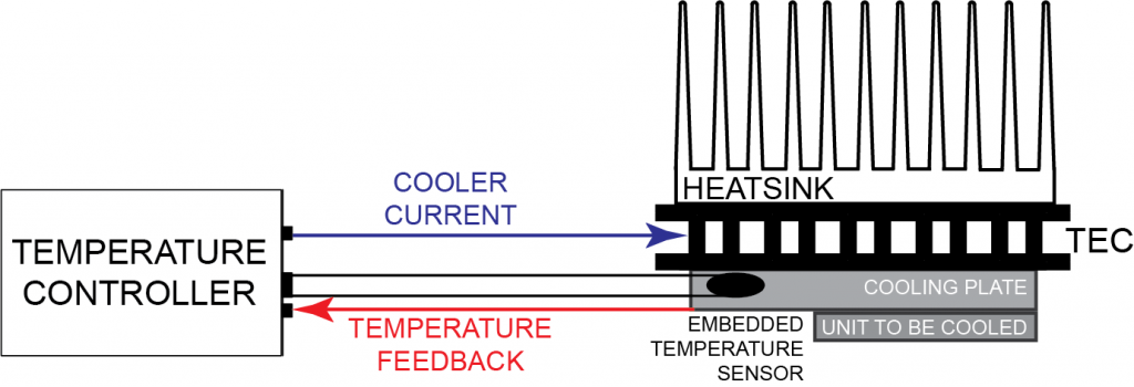
The operation of the temperature detector is to send the temperature signal to the monitor. The system has a small value of passing current, introduced as the Bias Current, which is controlled by the temperature monitor. The monitor cannot read the thermistor resistance, so it should modify the resistance variations to voltage outputs by employing a current source.
The operation of the temperature monitor is like the brain of the system. It archives the system information, compares it to the setpoint requirements, and regulates the current through the Peltier part to modify the temperature based on the setpoint.
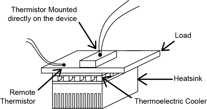
The installation of the thermistor in the system influences both the stability and precision of the measurement. The thermistor requires to be located as close as possible to the resistive heater for better reliability. On the other hand, it should be placed near the device temperature monitor for better precision. If the system is embedded, air gaps must be reduced using thermal glue.
The next diagram demonstrates two thermistors, one joined straightly to the system, and one is set remotely or distant from the main system. If the thermistor is too far away from the system, thermal lag time considerably decreases the precision of the temperature sensing.
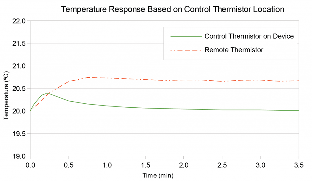
The next diagram presents the difference in temperature sensing operated by two thermistors. The thermistor, combined with the device, detected the variation of thermal load too quickly. The other thermistor also operated but not quite as immediately. This difference is too considerable when precise temperatures are needed.
When the location of the thermistor resistance has been selected, then the rest of the system requires to be optimized. This contains specifying the main thermistor resistance, the bias current of the device, and the reference temperature of the power on the temperature monitor.
Which Thermistor Resistance and Bias Current Should be Used?
Thermistors are determined by the amount of resistance at ambient temperature, usually 25°C. The system whose temperature requires to be fixed has specific technical features for maximum use, as presented by the designer. These should be considered before choosing a sensor. Thus, it is essential to learn the following:
What are the Maximum and Minimum Temperatures for the Device?
Thermistors are appropriate when sensing a single target temperature that is between 0 to 100 °C. If the temperatures are significantly low or high, the thermistor resistance will not operate properly. While there are some special exceptions, most of them generally perform completely in the temperature range between -55°C to +115°C.
As discussed before, thermistors are nonlinear instruments, so the resistance to temperature values are presented on a curve diagram instead of a straight line, and very low or very high temperatures are not documented appropriately. For example, small variations in high temperatures will not show proper resistance modification, which won’t provide voltage outputs accurately.
What is the Optimum Thermistor Range?
Each thermistor has an optimum beneficial condition based on the bias current derived from the controller. The next figure presents the most usable temperature ranges for thermistors at the two most usual bias currents.
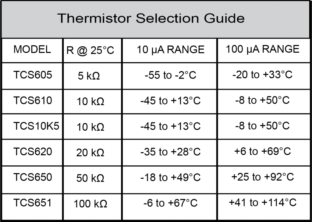
It is suitable to select a thermistor where the set-point temperature is in the center of the state. The sensitivity of the system is based on the temperature. A thermistor may be typically more sensitive at cooler temperatures like a TCS10K5 10kΩ thermistor. Its sensitivity is 165 mV/°C between -1 and +1°C, and 45 mV/°C between 24°C and 26°C, and 15 mV °C between 48°C and 50°C.
Conclusion
Thermistors are temperature-based resistors, modifying resistance with temperature variations. They are too sensitive depending on their material and respond to a few changes in temperature. They are the perfect choice when a particular temperature needs to be obtained and when controlling conditions within 50°C of ambient.
Thermistors are the complete method to sense and monitor cooling and heating. Their feature to regulate the temperature immediately permits them to have the greatest stability. Thermistors can be mounted on the system needing temperature control. They are applicable for solids, liquids, gases based on their type.
Buy Equipment or Ask for a Service
By using Linquip RFQ Service, you can expect to receive quotations from various suppliers across multiple industries and regions.
Click Here to Request a Quotation From Suppliers and Service Providers
Read More on Linquip
- What is the core difference between Thermistor and RTD?
- What is a Thermistor and How its Working ?
- Mastering Resistance Calculations: A Comprehensive Guide for Electrical Enthusiasts
- Difference Between Thermistor and Thermostat: which one outperforms the other?
- What is PTC Thermistor? (Applications & Advantages)
- A Complete Guide to Impedance and Reactance
- What is NTC Thermistor? (Types, Applications & Advantages)


