In general, various water turbo types have been developed to exchange energy between water flow and hydraulic machines. There are different methods for classifying turbo types; these methods include classifications based on the compressibility of the fluid passing through the machine, the fluid flow path in the wheel, how the wheel is fed by the fluid, how the static pressure changes, and how the energy is exchanged between the fluid and the machine.
Turbo Types Based on the Compressibility of the Fluid Passing Through the Machine
Accordingly, there are two types of turbomachines:
Compressible Fluid Turbomachines
In these machines, changes in fluid density occur with changes in pressure. Gas turbines, steam turbines, and compressors are classified in the first category.
Incompressible Fluid Turbomachines
In these machines, the fluid density remains constant during the energy exchange process. Pumps and water turbines are among the second category.
Therefore, from now on, we are facing only the second category, i.e., turbo types with incompressible fluids.
Turbo Types Based on the Fluid Flow Path in the Wheel
Based on this criterion, turbo types can be divided into three general categories:
Centrifugal or Radial Turbos
The fluid enters the impeller chamber through the radial vanes, which rotates. Therefore, the centrifugal forces draw the fluid towards the center, and the energy of the fluid and its pressure increase during this operation. Many well-known pumps in the industry are among these turbo types.
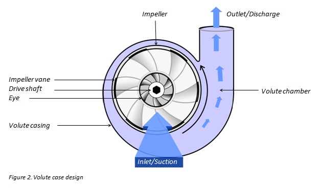
Axial Turbos
The turbo is axial when the fluid path is parallel to the axis of the machine. Kaplan turbines and some water pumps are among these turbo types.
Mixed Flow Turbos
Turbo types in which the pathway of the fluid contains both radial and axial components are called mixed flow machines. For example, the modern Francis turbine and also some pumps are of the mixed type.
Turbo Types Based on How the Wheel is Fed by the Fluid
There are two turbo types in terms of how to supply the fluid needed for the machine to operate.
Full Wheel Feeding
The fluid surrounds the entire wheel and enters it from the entire surface of the wheel. Like what we see in Francis or Kaplan turbines.
Partial Wheel Feeding
In such turbo types, Fluid enters the machine from one or more parts; like the Pelton turbine.
Turbo Types Based on How the Static Pressure Changes
Based on this, turbomachines are of two types:
Impulse Turbos
When the static pressure of the fluid remains constant while passing through the wheel, the rotary machine is of the impulse type. Similar to what happens to water during energy exchange with a Pelton turbine.
Reaction Turbos
The pressure changes as it passes through the wheels of these turbos; like the Kaplan turbine.
Turbo Types Based on How Energy Is Transferred
Based on the energy transferred from the source to the machine or vice versa, we have two turbo types:
Power Consumer Turbos
In this type of machine, mechanical energy is transferred from the turbo to the fluid. In other words, the power is traveled from an external source to the fluid to carry it. Pumps are one of these machines. Also, among compressible machines, compressors are a subset of them.
Power Supplier Turbos
In these machines, fluid energy is transferred to the machine so that the wheel rotates, and this process produces mechanical energy. Using a generator, this generated mechanical energy can be converted into electrical energy; like what occurs in water turbines.
In the following, we will further describe these two types of hydraulic machines, discuss their types, enumerate their main components, and give examples of their important cases.
Water Pumps
Pumps are machines that can transfer water from one location to another using an external energy source (motor). Naturally, adding power from an external source to water increases its energy. So, the pump is used to increase the pressure of a liquid.
Which pump should be used for a particular purpose depends on several criteria. One of these criteria is the amount of liquid to be pumped per unit of time; Also, the pressure required to reach the destination, the structure and design specifications of the hydraulic system, suspended particles and dissolved gases in the system, erosion, and flow corrosion conditions, along with fluid characteristics such as density, viscosity, and temperature affect the choice of the hydraulic pump in the system.
The mechanism of energy transfer from the pump to fluid is different among different types of pumps and therefore a single theory cannot be generalized to different types of these machines. Therefore, pumps are classified into different categories to facilitate the explanation and interpretation of the operation of pumps.
There are several ways to classify pumps; for example, based on the method of energy exchange, construction of the pumps, the use, or the fluid transferred by the pump. The most common method for this purpose is to classify based on the energy exchange procedure between the pump and the liquid.
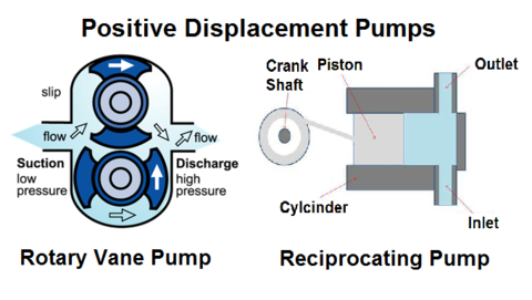
Displacement Pumps
The energy transfer to the liquids in these machines is discontinuous. Displacement pumps are divided into two categories: reciprocating pumps and rotary pumps.
Reciprocating pumps are available in diaphragm and piston types. A brief explanation of how these pumps work is that the rotating crankshaft causes the connecting rod to move in the same direction, and this reciprocating motion causes the piston to move. Moving the piston into the cylinder increases the fluid pressure.
Rotary pumps consist of a cylinder, several vanes, and a rotor which causes the centrifugal force, which drives the vanes toward the wall, creating a chamber between the rotor and the cylinder in which fluid can enter the chamber.
Further review of these pumps is not in the scope of this article. To read more, refer to this link about reciprocating pumps and this link about the rotary pump.
Dynamic Pumps
In these turbo types, the pumps continuously transfer energy to the liquid.
Dynamic pumps include turbopumps and peripheral pumps. We are dealing with the group of turbopumps here.
In the case of peripheral turbines, suffice it to say that these pumps have turbine-like impellers that increase fluid velocity by rotation. The especially built-in path also provides the conditions for converting velocity to pressure.
Turbopumps
Turbopumps or impeller pumps are a group of turbomachines that are considered to be the most widely used pumps in the industry due to their simple construction and flexibility. Their main components are a rotor and some blades on the rotating shaft, which increase the angular momentum of the fluid by the effect of the rotating blades on the fluid.
Also, low weight, low volume-to-power ratio, and no need to convert reciprocating to rotational motion are the advantages of these pumps.
Types of Turbopumps
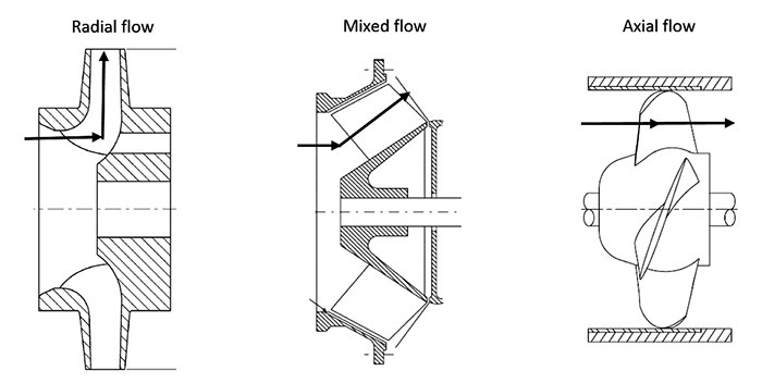
The most important types of turbopumps include single-stage or multi-stage pumps. Multistage pumps are used to increase fluid pressure in several stages. Pumps can be installed vertically or horizontally. The fluid flow path inside the pumps can be centrifuged, axial, and mixed.
In axial pumps used for lower heads, the inlet and outlet flow move approximately parallel to the wheel axis. The specific speed of an axial pump is 10,000 or greater.
In radial or centrifugal pumps, which are for high heads, the axes of flow at the inlet and outlet are almost perpendicular to each other. The centrifugal pump’s specific speed range is between 50 and 10,000.
In mixed pumps developed for medium heads, the input flow enters axially and the output flow exits at an angle greater than 90 degrees. They have specific speeds of about 35 to 160.
It should be noted that in cases where the head is very high, positive displacement pumps are a better choice than centrifugal pumps.
In the figure below, you can see the turbine wheel in three modes: centrifugal, axial, and mixed.
Components of Turbopumps
The construction of a turbopump consists of the following main components:
Inlet (Suction Element)
The suction part has an important effect on the velocity distribution at the impeller entrance, which can have various shapes depending on the use and type of turbine.
Rotor (Impeller)
This section is responsible for increasing the velocity and pressure of the liquid.
Diffuser
It is an optional part in pumps, the presence or absence of which in the set depends on the size and operating condition of the system. Its task is to convert the velocity of the fluid into pressure.
Volute
In centrifugal pumps, this section is located after the impeller or diffuser (subject to the presence of the diffuser), which maintains the velocity and directs the flow to the outlet.
Water Turbines
The basis of water turbines is the exact opposite of pumps; that is, using the energy in the water flow to spin the rotating unit of a turbine to create mechanical energy that can be converted into electrical energy. Turbines in industrial dimensions can operate in hydropower plants with different capacities. This experience was first demonstrated in 1880 in Wisconsin, the USA, in the generation of direct current in a small power plant.
One of the advantages of these turbines is that they do not have air pollution or thermal water pollution. Also, the long life, high efficiency, simple technology, and low cost of construction and maintenance of these turbines have been considered.
However, high initial costs, especially for low-head cases, concerns about the water hammer phenomenon and cavitation, erosion of water particles, and ubiquitous unavailability are some of the problems with using water turbines.
The history of the invention of water turbines dates back to ancient times in ancient Greece when the water wheel was the simplest form. The first industrial version of these turbines was built and developed around 1830 by a French engineer named Benoit Fourneyron, which achieved efficiencies above 80%.
The first radial flow turbine was developed by an American engineer named James B. Francis, which was used in primary use for heads between 10 and 100 meters.
Another example that received much attention was the invention of the American researcher Lester A. Pelton; an impulse turbine that, with the help of a nozzle, drives the water jet to the turbine wheel and discharges it at atmospheric pressure. That turbine was used for heads between 90 and 900 meters.
As most industrial turbines were still used for high-head cases in 1913, Viktor Kaplan designed a turbine suitable for smaller heads that looked like a ship’s blade but worked the other way around. Later, with the help of rotating blades, he improved his idea and achieved higher efficiency.
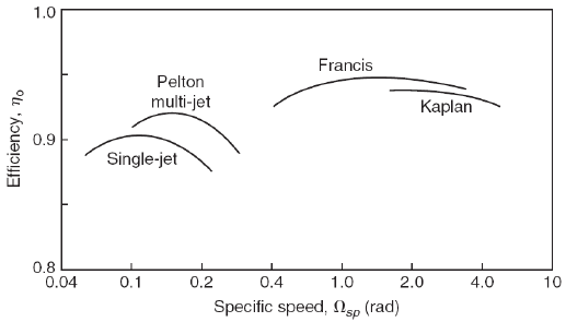
The amount of power generated by the turbine divided by the hydraulic energy delivered to the turbine per unit of time is known as the efficiency of a hydraulic turbine.
You can see the efficiency changes of different water turbines in different specific speed ranges in the figure below. Specific speed is an important criterion for selecting a turbine in different situations. Low-speed turbines are suitable for low volume and high head flows, while high-speed turbines are proper for low heads and high flows.
Pelton
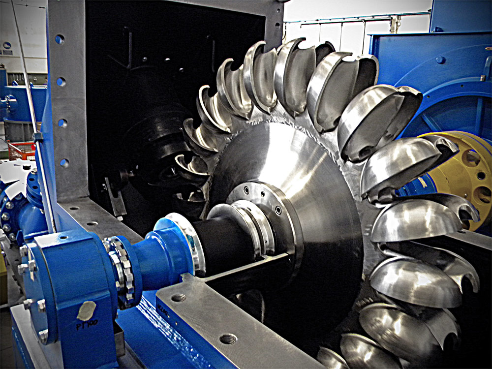
The most widely used impulse turbine is the Pelton turbine; A high-efficiency turbine suitable for high heads. The turbine spins by spraying high-speed water jet(s) into buckets with a splitter in the center to divide the flow into two parts; after hitting the center of the bucket, the flow exits from both sides of the bucket in an almost opposite direction for spraying.
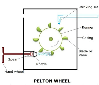
The turbine shaft is connected to a synchronous generator. When the network load is suddenly cut off, the servomechanism is used to stop the flow with the help of a spear to gradually cut off the flow from the nozzle. However, when quick actions are required, a deflector plate is used to prevent water jets from spraying on the buckets.
The figure below shows the Pelton wheel.
Francis
Francis turbines are reaction turbo types developed for medium heads and flow rates. The installation of these turbines is generally axial and in the case where the machine is smaller, it is vertical.
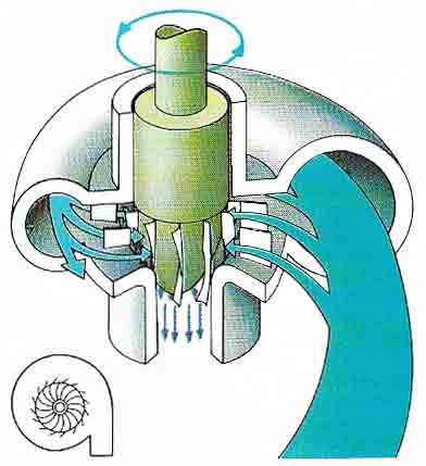
The flow first enters the volute that surrounds the runner. The diameter of the volute gradually decreases so that the velocity of the water flowing in it does not reduce. It then enters a row of stationary vanes that lead the flow in the appropriate direction to the rotating blades.
In the exchange of energy with blades, the necessary energy is delivered to the shaft. The flow is then directed axially to the tailrace. At this stage, the flow goes to the draft tube. The presence of that immersed tube is essential to help both the hydraulic head and the turbine wheel always be full of water.
The figure below displays the fluid flow path in the Francis turbine.
Kaplan
These turbines are reaction, an extended type of Francis turbine developed for lower heads. The wheels of these turbines are axial. However, the overall flow configuration is radial to axial due to the similarity of the structure of the Kaplan to Francis. An important feature of these turbines is that the blades of these turbines are adjustable.
Due to the requirements to generate a large amount of power, the volume of the inlet flow to these turbines is high. Therefore, a very high torque must be transmitted, and because the blades are long, the considerations needed to maintain their strength increase the chord length of the blades.
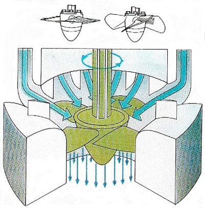
Pump Turbine
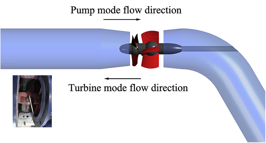
A pump turbine is a hydraulic assembly commonly used for energy storage (Hydraulic Energy Storage) purposes. Their structure is generally in the form of a Francis turbine. This set works between two reservoirs, one at the lower level and the other at a higher level.
At night or when the electric demand is high, the water flows from the upper reservoir to the lower one, meanwhile, the head needed to start the turbine is provided. During the day, when the consumption load is low and there is no need to start the turbine, it works in reverse, i.e. pump, and transmits water from the lower level to the upper one, which is the storage place for the turbine mode.
These machines are made in three general forms.
First, the pump and turbine are two separate machines.
The other category is to integrate the pump and turbine into one machine. There is a wheel that works both as a pump and as a turbine. These machines are also called PAT (Pump as Turbine). The most common types of these machines are centrifugal pumps, which operate in a reverse mode like a Francis turbine. However, they are also used in other types of axial and mixed machines.
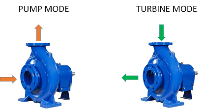
In the third category, the pump wheel and the turbine are integrated into two parts; such as the wheels of two-piece pumps, where one part of the wheel works as a pump and the other part works like a turbine.
Buy Equipment or Ask for a Service
By using Linquip RFQ Service, you can expect to receive quotations from various suppliers across multiple industries and regions.
Click Here to Request a Quotation From Suppliers and Service Providers
Read More In Linquip
- How do Valves work in an Engine?
- The Difference Between Gearbox and Transmission
- What is Gear Shaft? Clear Principle & Advantages
- The 10 Best Diesel Engines
- The efficiency of the Stirling Engine (Formula & Diagram)
- What is a Helical Gearbox?
- Differences Between Worm and Bevel Gear
- What is a Bevel Gear and How Does it Work?
- What is a Worm Gearbox?
- The Ultimate Guide to The Difference Between Gas Turbine and Reciprocating Engine
- Quick Guide: The Difference Between Gas Turbine and Diesel Engine
- What is Planetary Gearbox and How Does it Work?
- Beginner’s Guide: The Difference Between Gas Turbine and Gas Engine
- Differences Between Motor and Engine
- Differences Between Engine and Transmission
- Velocity Head: All You Should Know About Definition and Importance
- Hydraulic Head: All You Should Know About it
- Diesel Engine Working: everything you need to know



Interested in a type of turbine used in propulsion. Engine is designed to be completely submerged and be used on board something like a size of a supertanker of the type. I am currently designing something for transoceanic vehicle. Please send some information or point me to someone that can.
thank you.