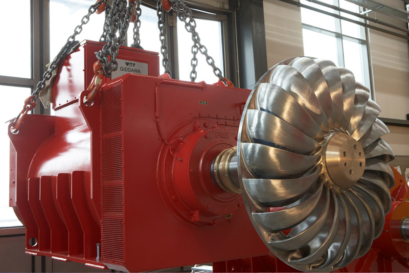
The Turgo turbine was first designed in 1919 by a young engineer named Eric Crewdson who graduated from McGill University in Canada. He came up with the idea of an impulse turbine with a diagonal water inlet in which one or two water jets struck with a runner at an angle on one side and discharged on the other.
This turbine usually operates at twice the speed of a Pelton turbine when operating on a head similar to a Pelton. Thus, the Turgo Impulse Turbine was invented and its patent was registered under the name of Mr. Crewdson.
In 1919 the first Turgo turbine with a capacity of 30 kW was installed in Scotland. This operation was quite successful.
In 1934, Gilbert Gilkes and Gordon, the turbine manufacturer, set up one of the first water turbine testing facilities in the United Kingdom, and in 1936 and 1960, the Turgo turbine was developed. Continuous testing that is still ongoing on these turbines has led to improved performance of these turbines.
So far, there are more than 1,000 units of these turbines installed in 65 countries around the world, operating at capacities of 25 kW to 10 MW.
Description of Turgo Turbine
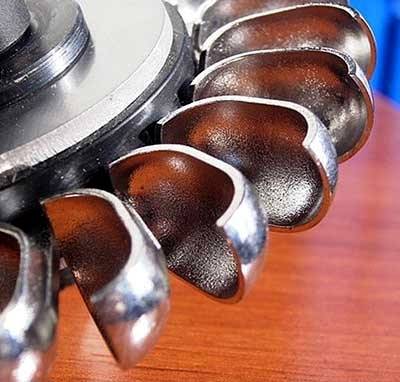
The Turgo turbine is an impulse water turbine that operates at higher flow rates than the Pelton turbine. One of the most important differences between the shape of a Turgo turbine and a Pelton turbine is that Turgo turbines use a single cup instead of the double buckets mounted on the Pelton wheel. Also, these cups have less depth. In the figure below, you can see the shape of Turgo turbine buckets.
Turgo turbine has smaller runners and faster rotational speeds than the other type of impulse turbines, Pelton. Therefore, in the case of some Turgo turbines, instead of using various ways and equipment to increase the speed, their shaft can be connected directly to a generator.
Turgo turbine can maintain its ability to deliver high efficiencies in a wide range of inlet water flow rates. This is not the case with many widely used industrial turbines, such as Francis. Therefore, the Turgo turbine can be considered as a reliable run-of-river turbine with high flow rate changes.
Turgo turbine is designed for applications with a medium range of head. Although the Turgo turbine is up to 90% efficient in laboratory tests, its efficiency in operating units is about 87%.
The specific speed range of the Turgo turbine is between the Pelton and Francis turbines. This parameter is between 8.5 and 30 for a single-jet Pelton; while Francis specific speed range is between 50 and 400. The number of nozzles in these turbines can be more than one, that is, it can be equipped with a single jet or twin jets; in the latter case, it increases the specific speed. In this way, four jets cause twice the specific speed that a jet creates.
The Turgo runner is like a Pelton runner which seems to be split in half. Therefore, for a similar amount of power, the diameter of the Turgo turbine runner is half the diameter of the Pelton runner, which doubles the specific speed of the turbine.
Another difference between this turbine and Pelton is that since the water coming out of each cup is not hindered by adjacent cups, the volume of water passing the Turgo turbine is more than Pelton.
Working Principles of Turgo Turbine
Since the Turgo turbine is an impulse type turbine, water pressure does not change as it passes through the runner. Turbine components operate at atmospheric pressure and water is discharged at this pressure. The development of the Turgo turbine is based on getting the maximum energy from the high pressure water flow.
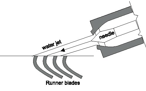
The potential energy of the water from the hydraulic head which has a high pressure is converted by the nozzle into kinetic energy, i.e. velocity. The high velocity water jet hits the cup-shaped turbine blades at an angle of about 20 degrees which after the collision, reverses the water flow and directs it outward. In the figure below, you can see how the water jet hits the turbo turbine buckets.
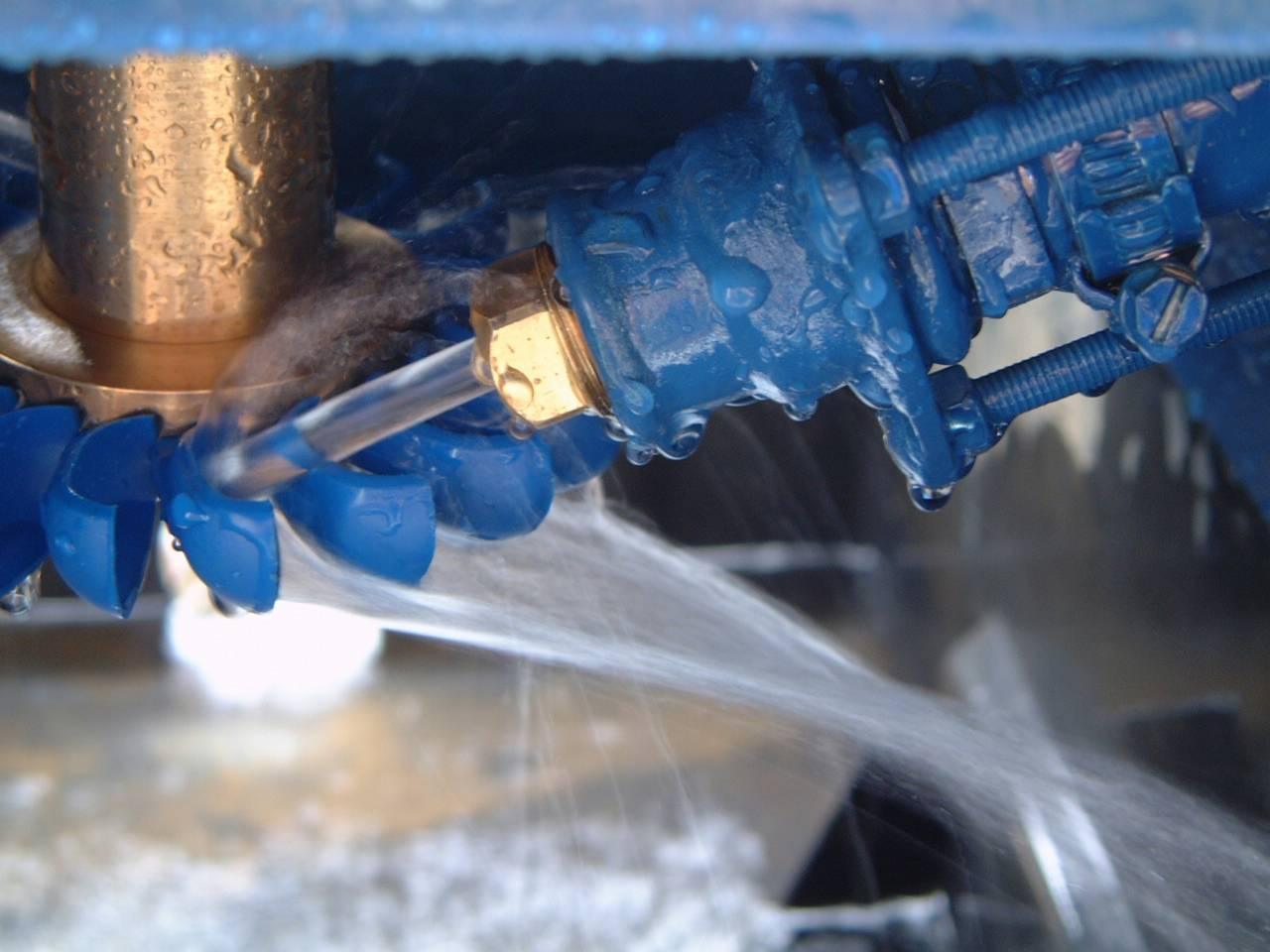
The created momentum causes the runner to rotate and the transfer of this energy to the turbine shaft causes mechanical work. Mechanical work is converted into electrical energy by a generator connected to the shaft. Because the shaft itself rotates at high speed alone, there is no need for intermediate shafts and gearboxes to increase the rotational speed caused by the turbine runner rotation.
Therefore, the following steps are taken when exchanging energy between the water and the Turgo turbine.
1- The water in the resource existing at a higher location than the turbine is transmitted through the Penstock pipe to the nozzle(s).
2- High water pressure is converted to velocity due to the special nozzle structure.
3- High-speed water hits the blades and causes the runner to rotate.
4- In cases where the turbine is not made for a fixed flow rate, the volume of water that hits the blades is controlled by the axial motion of the spear inside the nozzle.
5- The generator connected to the shaft converts mechanical energy into electrical energy without the need for a mechanism to increase the rotational speed, due to the high speed of the Turgo turbine wheel.
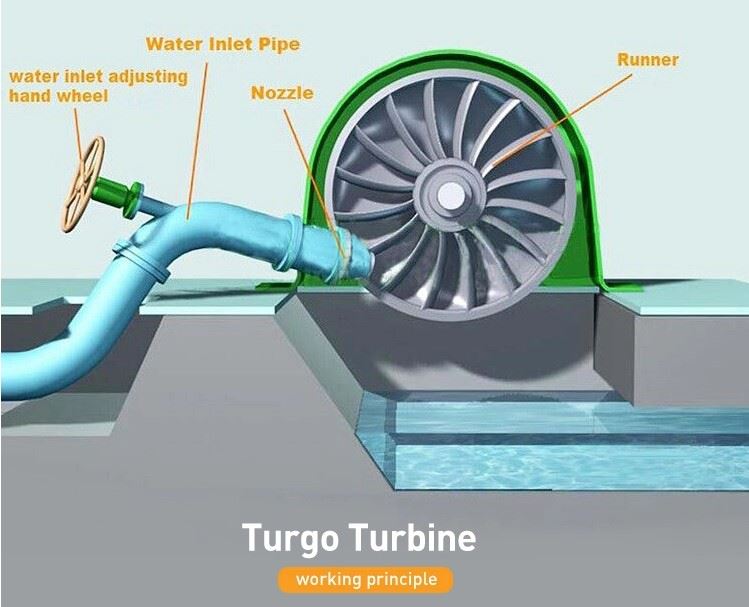
Components of Turgo Turbine
The main components of Turgo turbines are as follows.
Nozzle
The nozzle is responsible for converting high potential water pressure and energy into a high-speed water flow. In this impulse turbine, like a Pelton, a needle is used to regulate the amount of flow coming out of the nozzle.
This needle is a cone that moves manually or automatically in the axial direction. As the nozzle moves forward, the water jet decreases; and vice versa, as it moves backward, more water jumps from the nozzle towards the runner.
Some manufacturers of Turgo turbines use fixed jets without spears for constant flow rates.
The nozzles are made of tungsten carbide; this material has a high hardness and is resistant to the effects of corrosive and erosive particles.
Runner
A runner is a circular disk with a number of cups attached to it. In the center of the runner is a cylindrical shaft. Shafts and runners are made of stainless steel. Of course, for smaller heads, the runner is also made of cast iron.
Buckets
Buckets are blades mounted on the runner that when the water flow hits them and water comes out of the opposite side of each of them, momentum is created that rotates the runner. The buckets are made of nylon or stainless steel.
Casing
This part, which surrounds the turbine assembly, prevents water from splashing out. It also acts as a protector around the turbine. The casing is made of stainless steel or cast iron.
Breaking Jet
When the load is removed and the turbine continues to rotate despite the interruption of water flow from the nozzle due to inertia in the runner motion, a water jet is considered behind the runner bucket to throw water at it in the opposite direction of the runner rotation to stop immediately.
Penstock
In hydropower plants, penstocks are pipes and canals that are installed upstream of the turbine to transfer water from reservoirs and dams to the turbine. To withstand the high pressure water flows inside these pipes, the penstock is made up of steel.
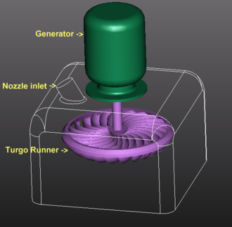
In the figure below, you can see the position of the nozzle and generator for the vertical installation of the Turgo turbine.
Advantages and Applications of Turgo Turbine
Here are some of the strengths of the Turgo turbine.
- The turbine has a simple structure and assembling the components of the turbine is simple.
- The runner of a Turgo turbine is less expensive than the Pelton runner.
- The installation position of Turgo turbines is both horizontal and vertical.
- Unlike the Francis turbine, it does not require an airtight housing.
- Cavitation as a common problem in reaction turbines does not occur in Turgo turbine; because, in these turbines, water only hits a specific part of the turbine blades and is only in contact with this part. As a result, there are no changes in pressure and bubbling in different parts of the runner.
- Due to the convenient material of the buckets and also the little contact of water flow with the runner, these turbines are reliable even for use against erosive, silty, and abrasive flows. As an example, Francis is susceptible to the wear phenomenon, while Turgo is not.
- Turgo turbine operates within the overlapping range of the Francis and Pelton heads. These turbines are more suitable for small-sized installations where the low-cost factor is important, although they are also used in large power plants.
- The number of Turgo turbine components is less, compared to other turbines in conventional power plants. Including guide vanes and volute parts in Francis or Kaplan turbines.
- The operating head range of the Turgo turbine is between 100 and 300 meters.
- Turgo turbine is able to maintain efficiency in a wide range of flow conditions. In fact, the efficiency diagram of these turbines is flat for different values of flow. In addition, the efficiency of these turbines is generally acceptable and relatively high.
- Compared to Francis Turbine, due to the hydraulic operating conditions of the two turbines, the Francis stops operating at lower currents, while the Turgo turbine continues to generate electricity.
- The power generating capacity of the Turgo turbine is up to 10 MW.
- The jets of the Turgo turbine are larger than the Pelton turbine, the volume of the wheel is smaller, and it can spin faster.
Disadvantages and Restrictions of Turgo Turbine
Below are some of the weaknesses of the Turgo turbine.
- The generator and powerhouse needed to operate the Turgo turbine are large.
- Controlling changes in the head is somehow difficult due to working in medium heads.
- The operating range of this turbine does not include very high or very low heads and flows. The optimal conditions for installing these turbines are in situations with relatively high hydraulic heads with low flow rates.

