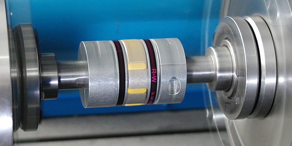
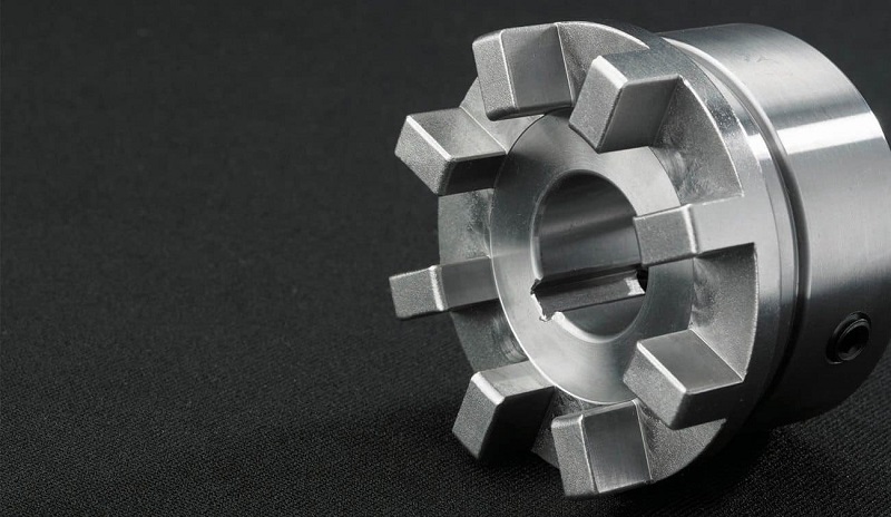
A coupling is a mechanical gadget that is utilized to join one shaft to another. Couplings find a use for power and torque transmission between two rotating shafts such as on motors and pumps, compressors, and generators. Couplings have many different designs and working principles each one has its characteristics and certain applications to serve. Coupling type design factors are in many variables, such as horsepower, load, specific gravity, head pressure, torque, shaft installation, shaft size, shaft maintenance, safety factors, etc.
In this article, we will dive into the various types of coupling and pointing out the main differences between them. Find out about the types of coupling and which one will best suit your needs. Read this new blog in Linquip to find out more about them.
What Are The Different Types Of Coupling?
Couplings depending on the alignment accuracies of the system and torque requirements can be generally categorized into three varieties: Rigid, Flexible, and Fluid which are used to transmit power. While each coupling type has its advantages and disadvantages, it’s important to know which coupling to choose in a particular application. Types of coupling are quite unique in their construction and we discuss in detail their constructional and working aspects. So let us start!
Rigid Coupling
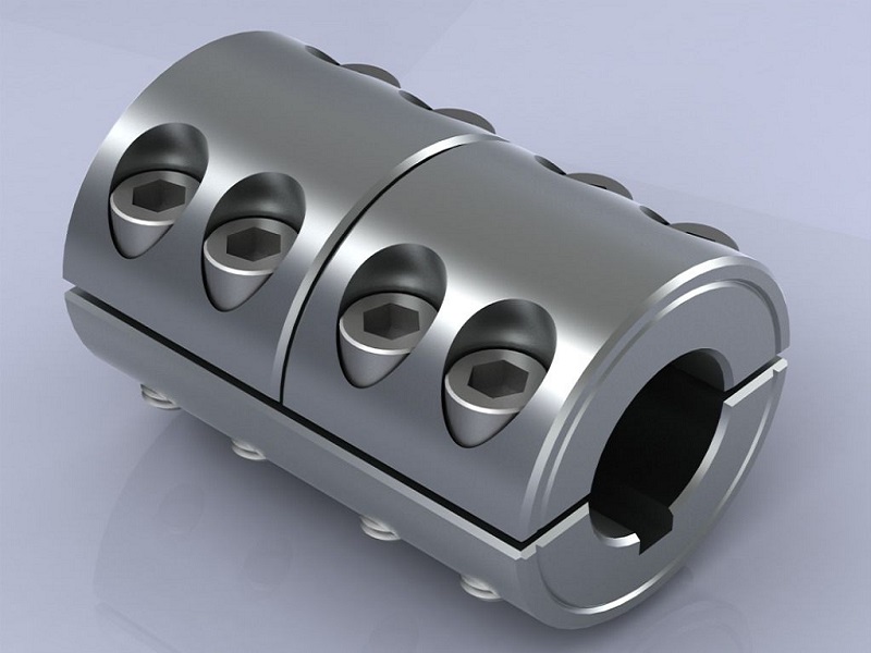
Rigid couplings connect two shafts with a solid and high-precision-aligned hold. Rigid couplings have been historically economical, and frequently homemade segments for the straightforward shaft-to-shaft associations. To be considered rigid, a coupling would allow less than one degree of deflection or angular movement.
This type of coupling has no flexibility or resilience, hence the shafts must have good initial alignment and stable support bearings to ensure good performance. It must be aligned both laterally and angularly, in order to avoid damping transmission, possible breaks in the installation, and excessive loads on the shafts, or the shaft bearings.
Rigid couplings work best for high-torque requirements, shaft support applications, and push-pull use cases. These couplings are used in applications where a rigid joint is desired, similar to that of a traditional flanged, welded, or threaded connection.
Characteristics
- The coaxial degree between the two shafts of the loading time is strict.
- They can suit a slight misalignment between shafts of about up to 0.5-degree precise misalignment and 5 mm hub misalignment.
- The radial pulsation is not greater than 0.03.
- The axial core tilt is not more than 0.05/1000.
Advantages
Rigid couplings provide several advantages that make them the preferred choice for many projects. Some of their key advantages include:
- This coupling can efficiently transfer torque from one shaft to the other connected shaft.
- Manufacturers can produce standard and custom rigid couplings at cost-effective rates.
- Precision, with nearly zero windup and zero backlashes.
- In this coupling high torsional stiffness allows for better positioning.
- Simplicity
- It can be used to establish shaft alignment between the motor and connected components.
- Easy assembly, disassembly, and maintenance operations throughout the life of the coupling.
Disadvantages
- They can’t adjust for any thermal changes.
- They are more limited in applications as compared to flexible couplings.
- They cannot absorb vibrations.
- They require lubrication many times.
- They can’t be kept running at very high rpm.
Flexible Coupling
Flexible couplings, which make up 90% of couplings sold, are designed to transmit torque from one shaft to another when the two shafts are slightly misaligned while permitting radial and axial displacement and rotation. To be considered flexible, a coupling must handle parallel and angular misalignment. These couplings also attenuate the transmission of fluctuation of torque and speed from one rotor to the other by flexing itself and are thus helpful in providing a nearly smooth transmission of speed and torque.
We can obtain a wide range of torque capacity depending on the type of flexible coupling. These types of coupling are used in applications that call for curved or deflected layouts or when systems are exposed to outside forces beyond normal static conditions, such as seismic events or where vibration or noise attenuation are a concern. Flexible couplings can be used in servos with low or moderate torque levels and the potential for shaft misalignment.
Applications: Machining tools, semiconductor manufacturing, and packaging equipment
Characteristics
Flexible coupling can accommodate a slight misalignment between various types of load and shafts up to 1.5-degree angular misalignment and 5 mm axial misalignment.
- They are made of a piece of solid metal.
- They often have more components and are more complex.
Advantages
- They compensate for misalignments, movement, or deflection.
- They are very useful when having quick and short starts.
- They are highly capable of reducing the transmission of shock loads or vibration.
Disadvantages
- They normally provide less torque transfer.
- They have a high cost due to additional parts.
- They don’t reduce backlash to at-zero levels.
- They have more complicated operations and maintenance.
Fluid Coupling
Fluid couplings consist of a housing containing an impeller on the input or driving shaft and a runner on the output shaft. Both of these contain a fluid which is usually oil that is added to the coupling through a filling plug on the housing. The components of fluid couplings are generally made out of metallic materials-aluminum, steel, or stainless steel.
These couplings offer the engineer real advantages, in many different kinds of power transmission. As a method of transmitting rotational mechanical drive power, a fluid coupling offers the advantages of soft starting of the load, torque limitation, and mechanical shock absorption, all with minimal energy loss. They are useful when an application requires variable speed operation and a startup without shock loading the system.
Application: Automotive, railroad, aerospace, marine, and mining industries. Forklifts, cranes, pumps of all kinds, mining machinery, diesel trains, aircraft, rotationally-powered industrial machinery, belt conveyors, extruders, centrifuges, bucket elevators, ball mills, crushers, mixers, slurry pumps, compressors, industrial fans, feeders, diesel locomotives, wagon tipplers, boiler feed pumps, reciprocating pumps, process pumps, dryers, etc.
Characteristics
- Steps less speed variation in scoop tube-type fluid couplings.
- There is no mechanical contact between the driving shaft and driven shaft (or between the pump wheel and turbine wheel).
- Operates in both vertical and horizontal applications.
- No-load start-up of motor or engine irrespective of machine load.
Advantages
- Sequential starting of multiple motors to reduce the aggregate value of current drawn.
- Smooth and controlled acceleration of large inertia-driven machines by a simple squirrel cage induction motor.
- Motor selection to operating duty/load rather than starting loads resulting in lowering capital cost.
- Overload protection for motor and driven machines by limiting maximum torque to a predetermined safe value.
- High efficiency due to low slip at rated duty.
- Power transmission is smooth. Controlled start-up speed without shock loading of the power transmission system.
- Due to the absence of a mechanical connection between the input and output elements, there is no frictional wearing of them.
- Effective dampening of shocks, load fluctuations, and torsional vibrations. Fluid coupling can run smoothly even in extreme conditions.
- The power transmission is free from vibration. There is no chance of vibration noises when power is transmitted from the vibrating engine to the driven shaft by using a fluid coupling.
- Automatic unloading of prime mover in case of sustained overload due to response (blowing off) of fusible safety plug.
- Simple control of torque by changing the fill level. The maximum torque can be adjusted by varying the amount of operating fluid filled in the casing.
Disadvantages
- It cannot develop torque when the driving shaft and driven shaft are rotating at the same angular velocity.
- There is always slip. There is always a slight difference in the speed of the pump wheel and turbine wheel
- The fluid-filled casing must be compatible with the coupling component, it directly affects the transmission behavior of the fluid coupling.
- Under stalling conditions, the coupling dissipates energy as heat it may lead to damage.
There are many types of coupling available in the market having their own importance in different parts of the transmission. How to choose the coupling that can meet the requirements of the machine from various couplings with various varieties and different performances, can be problematic.
Once the coupling type is selected, there may be variations to consider within that type. It is always a good idea to understand as much as possible about the two pieces of equipment to be connected. Let the driven equipment and the driver dictate the needs of the coupling. The right type of coupling must be chosen for your specific application to ensure maximum uptime and prolonged reliability for your equipment.
So, there you have every single fact to the different types of coupling. If you enjoyed this article in Linquip, let us know by leaving a reply in the comment section. Our experts have specialized knowledge in couplings and can provide recommendations and solutions based on your coupling needs. If you would like to learn more about how to select the right coupling for your equipment or operation, please feel free to sign up on our website to get the most professional advice.
Buy Equipment or Ask for a Service
By using Linquip RFQ Service, you can expect to receive quotations from various suppliers across multiple industries and regions.
Click Here to Request a Quotation From Suppliers and Service Providers
Read More on Linquip
- What Is a jaw Coupling? With the Focus on the Working Principle, Size & Dimension
- What is Grid Coupling? Essential Details You Need To Know
- A Cheat Sheet For The Types of Pump Couplings
- Advanced Guide: Types of Rigid Couplings
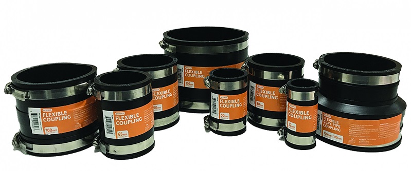
- The Quick Guide To The Types of PVC Couplings
- Types of Shaft Couplings: A Simple Guide to The Types
- What is Disc Coupling: A Complete Guide
- The Complete Library of Types of Flexible Coupling
- Types of Gear Coupling: a Basic Yet Crucial Description of the Types
- What Is a Fluid Coupling? Diagram + Parts
- Flange Coupling Adaptor: Working Principle and Applications
- What Is a Sleeve Coupling? Everything You Need to Know


