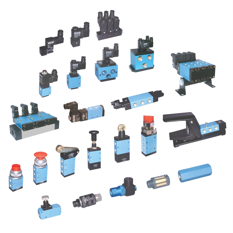
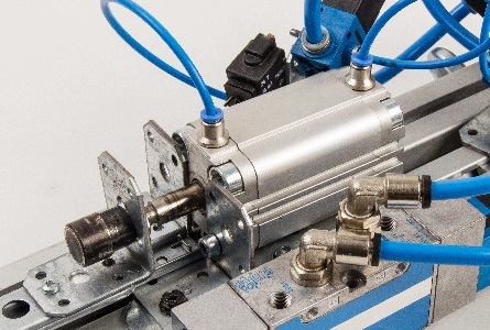
Types of pneumatic valves_ Valves are used to distribute, control, and direct the flow in this structure. They have a guiding and dosing function by locking and regulating components. Thus, pneumatic valves act as a mediator between the source (compressor) and actuators (such as a pneumatic actuator, pneumatic cylinder) in pneumatics.
In a pneumatic system, a Pneumatic Valve is a device that modulates or controls the flow of air (or another gas). In an automated pneumatic system, they function by controlling the air or gas at the source and regulating its passage as needed into pipes, tubing, or devices. Industrial Tools are used to make Pneumatic Valve, which is an important product. Pneumatic Valves are available from a variety of suppliers and companies, as well as various Manufacturers and distributors, and there are many Pneumatic Valves For Sale on Linquip.
There is a comprehensive list of pneumatic valve services on the Linquip website that covers all OEM fleets. Linquip vendors can support you with this. Please contact Pneumatic Valve Experts in Linquip to learn more about how to connect with a diverse group of service providers who consistently deliver high-quality products.
Special signals drive such valves. The following types of pneumatic valves are:
- air operated
- mechanical
- electromagnetic
⇒ View a Comprehensive List of Valves and Their Suppliers ⇐
Pneumatic Valves Meanings
The term “pneumatic valve” usually has two separate contexts of use that require some explanation. In the first context, a pneumatic valve is a mechanism that is used to modulate or control the flow of air (or another gas) in a pneumatic system. They work by controlling the air or gas at the source, regulating its passage as needed into pipes, tubing, or devices in an automatic pneumatic system.
The actuation element that makes the pneumatic valve open or closes might be performed in any of several ways, including electrically via a solenoid or motorized actuator, manually, mechanically, or pneumatically. The key theory to note in this example is that it is pressurized air or gas that is being managed and passing through the valve ports in the pneumatic system.
In the other context, the air is being utilized as the control tool on the valve, but the fluid that is passing through the valve ports is something other than air, maybe water, oil, or some other fluid. In this context, the pneumatic valve operates to present flow control in a valve, but the fluid existing in the lines is not air. The air serves as the control fluid, a flow in a pneumatic actuator to open, close, or modulate flow. These valves are consequently referred to as pneumatically-actuated valves.
To summarize, in the first context, the air is being controlled but may or may not be performing the control mechanism of the valve. In the second context, the fluid other than air is controlled, and the control mechanism is air. A distinction between these two prevailing contexts will help further understand pneumatic valves and their uses. The types of pneumatic valves are frequently representative of the first context.
Pneumatic Valve Designations and Configurations
Within the widespread classification of pneumatic valves such as two-way, three-way, and four-way, various valve configurations reflect the parameters named ports, switching positions, and non-actuated state. A standardized numbering system is typically used when defining these configurations, including two numbers separated by a slash (/). The first number is the port number in the valve, while the second number shows the number of switching positions. For instance, a 2/2-way pneumatic valve is a device that has two ports and switching positions. A 3/2-way valve is one with three ports and two switching positions.
Within these alternatives, there is also the topic of the non-actuated state. A 2/2-way valve can be prepared in a normally closed and normally open position. Normally closed means that the valve is closed when it is un-actuated and does not pass airflow between the ports. For opening the valve, actuation is required.
In a normally open valve, the reverse is true. Without actuation, the valve permits airflow and needs actuation to close off the valve.
In three-way valves, one port is regularly open. In such cases, a closed resting state usually blocks the airflow port, so air is not flowing unless the device is turned on. For example, a five-port three-position valve has port 1 as its pressure inlet, ports 3 and 5 as work ports, and ports 2 and 4 as exhaust ports.
Arrangements for pneumatic valves that are regularly used are 5/3, 5/2, 4/2, 3/2, and 2/2.
We have spring offset or detented pneumatic valves. In spring offset valves, the valve will get back to the starting state or condition when the actuation is eliminated. In detented valves, the valve will stay in the last actuated position until it is changed again by the operator.
Pneumatic Valve Specifications
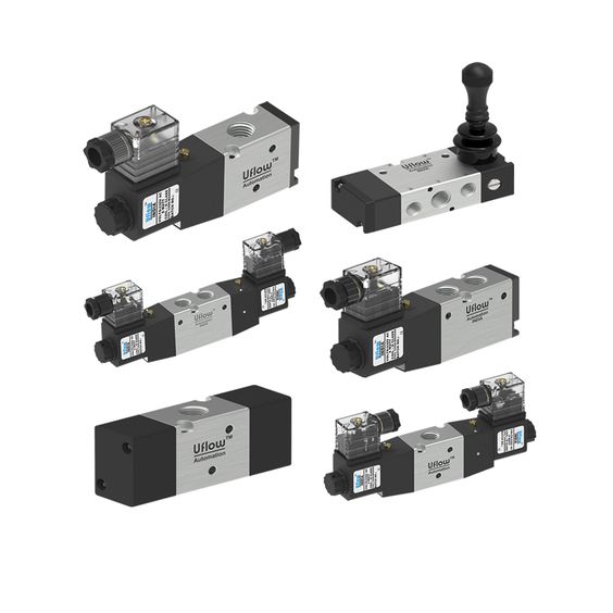
We have some specifications for pneumatic valves, some essential ones of which are reviewed below. These parameters are for overall guidance, and you should know that each valve manufacturer and supplier may describe their valves separately. Furthermore, the precise specifications are based on several parameters such as desired porting, the manifold design, and the actuation mechanism for the valve.
- Operating pressure or pressure range: the pressure amount or range of pressures the valve is rated to handle ( in psi, Bars, or Pa)
- Operating medium: the varieties of fluid that the valve can safely control. In most devices, it is compressed air.
- Flow capacity or flow coefficient: a measure of the capacity of the valve to pass or flow air through it, with the flow coefficient (Cv) expressing the proportionality constant between the flow rate and the differential pressure.
- Response time – the period of time needed for the valve to change states or positions when actuated.
- Cycle rate – the highest number of valve cycles at which the valve can work per unit of time.
- Coil rated voltage: in electrically actuated valves, a ratio of the maximum voltage that the actuation coil can provide and may be measured in DC and AC volts.
- Port size: the physical dimensional parameters specify the port sizes on the equipment and the thread style.
Types of Pneumatic Valves
Pneumatic valves, also named directional control valves, may be arranged using several different methods, which include:
- by the number of flow ways or switching positions that are possible
- by the number of inlet and output ports they possess
- by the mechanism that is applied to open or close the ports
- by the status of the valve when in the un-actuated state
Functional directional control valves, those that control the direction of airflow or inhibit flow altogether, are a large class of pneumatic valves that houses multiple variants. These devices can be used in various ways in a hydraulic system, such as to connect or disconnect the main compressed air supply from the system or to advance or retract air cylinders that move as part of the machine or process for which the pneumatic system has been created.
With this in mind, we can broadly delineate the primary types of pneumatic valves as:
- Two-Way directional control pneumatic valves
- Three-Way directional control pneumatic valves
- Four-Way directional control pneumatic valves
- Spring offset pneumatic valves
Directional-control valves are vital in any pneumatic circuit, directing or blocking airflow to control the speed or sequence of operations. One method of classifying directional-control valves is by the flow paths under various operating conditions. Important factors are the number of possible valve positions and the number of ports and flow paths. Here are some basic configurations.
Two-way, Two-Position Valves
Consist of two ports connected with a passage that can be opened or blocked to control flow through the valve. Usually, an electrically activated solenoid shifts the valve spool or poppet to direct flow. The valve provides an easy on-off function, which many systems use to interlock, isolate and connect various system parts.
Three-Way, Two-Position Valves
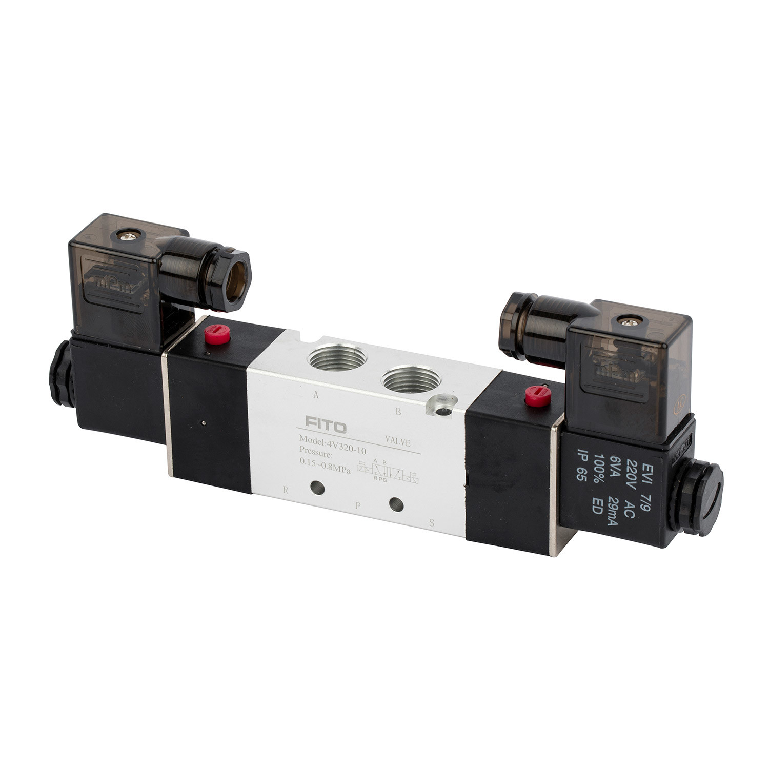
consist of three ports connected through passages within a valve body. The valves pressurize and exhaust one outlet port to control a single-acting cylinder or pilot another valve.
Three-way valves direct pressurized air to the cap-end side of the cylinder. Shifting the spool to the other extreme position blocks flow and pressure to the actuator. The actuator is connected to the exhaust passage; therefore spring force or gravity must return the rod to its original position.
Three-way valves may also be used in pairs to operate a double-acting cylinder, thus replacing a four-way valve. Consider using paired three-way valves instead of a four-way when high cylinder speeds are necessary. Close coupling of three-way valves to the cylinder ports reduces cylinder backpressure and pressure drop in the lines, permitting higher cylinder velocities. The valves are also used to save compressed air in high cyclic applications or when intermediate positions are required.
Four-Way, Two-position Valves
have four or five ports with two or three positions. A two-position valve has two distinct flow paths in each position to actuate and reverse cylinders, rotary actuators, or bidirectional motors. The spool directs flow from the pressure port while the other actuator port exhausts to the atmosphere at the same time.
In the five-port version of the two-position, the four-way valve has five individual ports, which provide various valve configurations such as two different exhaust or pressure ports. In the latter case, for example, the valve might supply high pressure to actuate a cylinder and provide high clamping force but deliver lower pressure (from a regulator) to release the clamp. Using lower pressure conserves energy.
Four-Way, Three-Position
valves are also available in five-port versions. The most common center conditions for these valves are “all ports blocked” and “exhaust center.” The two extreme positions of the four-port, four-way valve are the power positions of the valve which control actuator movement. The center position is designed to satisfy some system requirements, such as locking an actuator or letting it float.
Spring Offset Pneumatic Valves
This type of pneumatic valve classification refers to the manner in which airflow direction is switched. For example, in a two-way directional valve, the valve is either open (airflow is enabled) or closed (airflow is prevented). In order for each port to assume an open or closed position, an actuator moves a valve spool into position. To release the valve spool and return the pneumatic valve to its previous position, a spring releases the spool. A two-way directional valve that functions in this manner is also called a spring offset valve.
See All Solenoid Valve for Sale
Types of Pneumatic Valves Based on Actuators
the pneumatic valves can be categorized based on the types of actuators they use. They can have electromagnetic, air-operated, or mechanical actuators.
Solenoid Valves
Solenoid valves are designed to open and close in response to an electric signal. They control airflow in a pneumatic system and liquid in a hydraulic one. You can get either a valve with a spool or poppet arrangement.
Generally, solenoid valves are used in industrial workplaces for manufacturing. The reason is for the valve to work properly, it needs a consistent temperature. If you want one to work in a constantly changing atmosphere, the valve must handle temperature extremes so as not to short out.
An example of the latter would be in a car, where it’s used to start the ignition. When you turn your key, an electric signal is sent to open the valve and start the engine. The valve has to handle the emergence of heat from the engine and any cold from unfavorable weather conditions.
Other applications of solenoid valves include irrigation systems and dishwashers when referring to how they are used with fluids. They control the flow of water to allow for regular waterings of fields or cleaning your cups and plates, respectively. People value these models’ versatility and durability.
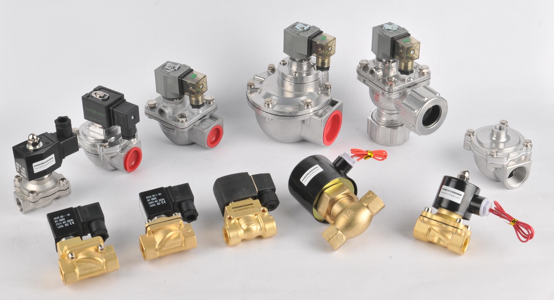
Air Operated Valves
Air-operated valves from a design standpoint are shaped similarly to those used in solenoids. Instead of receiving an electric signal, however, they respond to air pressure applying force to a piston or diaphragm.
You will see air-operated valves in environments that demand a high output but don’t want to rely on electricity and who wish to use them remotely. They are thus used in chemical factories and fertilizer manufacturing facilities. Regarding the former, chemicals, if exposed to the wrong substances, can induce combustion and endanger their operators. In the latter, people are kept far from potentially noxious nitrogen compounds.
Mechanical Valves
Mechanical, or hand-operated valves, use manual power. You may see them in operations where electricity would be dangerous or impractical for the tasks at hand. As with solenoid valves, they can be used for either air or liquid flow.
Usually, you apply energy to these valves using your hand or feet to move them. The operator would need to apply a push-pull motion or simply press a button with their palm. Other types of mechanical valves are powered by lever arms or with the power of friction. These days, mechanical valves have to be a larger size to handle a higher flow rate.
An example of a mechanical valve would be those used to help people with heart disease. They assist in helping ensure that blood and oxygen flow through the human body. While such artificial hearts risk blood clots, they increase a person’s lifespan with durable models.
Another would be a manual valve used in an older machine that has no electrical connection. Consider how old-fashioned sewing machines and spinning wheels would work by the user pressing a pedal; the energy would be transferred in a circular motion. They would use rudimentary pneumatics.
What Is a 3 2 Pneumatic Valve?
A pneumatic valve, also known as a directional control valve, controls the flow of compressed air or other gasses inside a system by blocking or diverting it. These valves are used to pilot other valves and to drive other components such as an actuator, gripper, hand tool, or other devices.
Pneumatically, manually, mechanically, or electrically through a solenoid valve, a 3/2-way valve has three ports and two settings. They can be used to regulate a single-action cylinder, drive pneumatic actuators, blow-off, pressure release, and vacuum applications, among other things.
Advantages of Pneumatic Systems
Pneumatic systems are intended to use compressed air to both transmit and control energy. Pneumatic systems can be seen in production lines, train doors, and mechanical clamps. Many industrial companies would not be able to proceed to work without the specialization of pneumatic control systems. In many cases, pneumatics is the driving force of automated machines. Some of the benefits of using these devices include:
- Systems that operate on compressed air do not run out of air because there is an infinite amount in our atmosphere, which can be used to provide compressed air. Distance does not restrict the transporting of compressed air and can be transported through pipes easily. Compressed air does not require to be recycled or processed when discharged back into the atmosphere.
- The instruments are durable and reliable. Components of these machines, same as pneumatic valves, are not damaged easily compared to other electromotive elements.
- These devices are safe to work. As opposed to electromotive systems, pneumatics systems are usually considered the safer of the two varieties. This is mainly because pneumatic systems are free of spark or explosion, which indicates they can work in combustible environments.
- Pneumatic systems do not overheat or burn when overloaded compared to an electromotive component.
pneumatic controlling system (Reference: rowse.co.uk)
Buy Equipment or Ask for a Service
By using Linquip RFQ Service, you can expect to receive quotations from various suppliers across multiple industries and regions.
Click Here to Request a Quotation From Suppliers and Service Providers
Download types of pneumatic valves PDF
Visit here to know the different Types of Pneumatic Valves.
Read More on Linquip
- Control Valve Suppliers and Companies in United States
- Audco Valves Suppliers and Companies
- Globe valve types: basic types plus bold pros and cons
- Control Valve Types101: Different Classifications, Advantage and Disadvantages
- Types of Hydraulic Valves and Their Working Principles
- Valve Manufacturers
- Control Valve Manufacturers
- Check Valve Manufacturers
- Needle Valve Manufacturers
- Butterfly Valve Manufacturers
- What is Knife gate valve
- What is Mixing valve
- What is Needle Valve
- What is Pinch Valve
- What is Piston valve
- What is Drain Valve? Working Principle, Types & Applications
- What are Coaxial Valves? Working Principles and Type
- What is Isolation Valve? Working Principle & Types
- Backwater Valves: Working Principles & Types
- What is Block Valve? Working Principle & Types
- What is Pilot Valve? Working Principle & Types (Complete Guide)
- What is Poppet Valve? Working Principle, Types & PDF
- What is Manifold Valve? With Function & Types
- What is Balancing Valve? Working Principles,Types & Function
- What is Air Valve? Working Principles & Types (Clear Guide)

