Types of propeller is the major part of understanding basic concept of propellers. A propeller is a piece of equipment with a rotating hub and radiating blades set at a pitch to produce a helical spiral that, when rotated, acts similar to Archimedes’ screw. It converts rotational power into linear thrust by pulling a working fluid, such as water or air.
Whether you are looking for the basics or the most advanced propellers, Linquip has everything you need. If you have any questions about propellers, our experts will be happy to help. To gain a basic understanding of these industrial devices, please review Linquip’s article entitled “Hydro Turbine.”
Hydro turbines are used for a variety of purposes. Are you familiar with them? Linquip’s selection of Hydro Turbine Products will help you find the right turbine for your application. Are there any particular types of hydro turbines you are interested in? Throughout Linquip, you can access all Hydro Turbine Devices for Sale for free. You can also inquire/request quotes from all Hydro Turbine Suppliers and Companies for free when you’re looking for turbine prices through Linquip.
The blades’ rotational movement is transformed into thrust by generating a pressure differentiation among the two surfaces. A delivered mass of working fluid is accelerated in one direction, and the craft travels in the opposite direction. Like aircraft wings, propeller dynamics can be modeled by Bernoulli’s principle and Newton’s third law. Screw propellers with helical blades are the most used marine propellers revolving on a propeller shaft with a nearly horizontal axis.
Historical Developments of Propellers
The principle applied in adopting a screw propeller is obtained from sculling. A single blade is passed through an arc in sculling, from side to side taking care to keep performing the blade to the water at the practical angle. The novelty presented with the screw propeller was expanding that arc through more than 360° by connecting the blade to a rotating shaft. Various types of propellers can have a single blade, but there are almost always more than one to balance the practice forces.
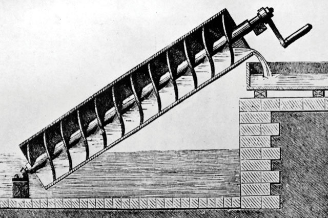
Screw Propellers
Although there was considerable experimentation with screw propulsion until the 1830s, few of these devices were attempted on the testing stage, and some were determined inadequate for one reason or another. In 1835, two creators in Britain, John Ericsson, and Francis Pettit Smith, started operating individually.
Smith was leading to take out a screw propeller patent, while Ericsson, a gifted Swedish engineer then operating in Britain, filed his patent six weeks later. Smith promptly built a tiny model boat to test his invention, which was proved first on a pond at his Hendon farm. Next at the Royal Adelaide Gallery of Practical Science in London, where it was recognized by Sir William Barrow.
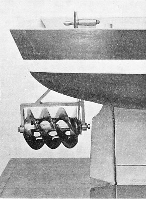
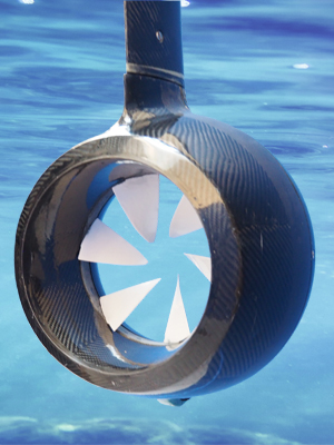
Shaftless Propellers
Wright brothers pioneered the twisted aerofoil shape of modern aircraft propellers. While some earlier engineers had endeavored to model air propellers on marine propellers, the Wrights recognized that an air propeller is quite the same as a wing and could utilize data from their more initial wind tunnel experiments on wings.
They also offered a twist along the length of the blades. This was necessary to ensure the blades’ angle of attack was kept nearly constant along their length. Their unique propeller blades were only about 5% less effective than the modern equivalent, some 100 years later. The recognition of low-speed types of propeller aerodynamics was complete by the 1920s, but later requirements to manage more power in more miniature diameter have made the obstacle more complicated.
Material and Construction of Propeller
Marine propellers are manufactured from corrosion-resistant materials as they are made operational in seawater which is a corrosion accelerator. The materials utilized for making marine propellers are an alloy of stainless steel and aluminum. Other popular materials employed are alloys of nickel, bronze, and aluminum, which are 10~15 % lighter than other materials and have higher durability.
The propeller’s construction process involves connecting several blades to the hub or boss by forging or welding in one piece. Forged blades are highly stable and have higher strength but are costly compared to welded ones. A marine propeller is assembled by sections of helicoidal surfaces acting together to twist through the water with a screw effect.
Types of Propeller
Propellers are divided based on several factors. The classification of various types of propeller is described below:
Classification by Number of Blades Attached
Propeller blades may alter from 3 blade propeller to 4 blade propeller and sometimes even a five-blade propeller. Nevertheless, the most regularly used are three-blade and four-blade propellers.
However, the most commonly used are four blades and five-blade propellers. The propeller efficiency is the highest for a propeller with a minimum number of blades, i.e. two-blade propeller. But to obtain strength factor and to consider the heavy loads subjected by the ship, sea, and weather, two-blade propellers are not applied for merchant ships.
Three-blade propeller
A three-blade propeller has the following features:
- The manufacturing cost is cheaper than other types of propeller.
- They are typically made up of aluminum alloy.
- The acceleration is better than the other types of propeller.
- Low-speed handling is not much effective.
- They give a reliable high-speed performance.
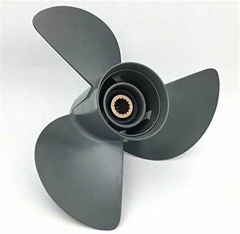
Four-blade propeller
A four-blade propeller has the following features:
- The manufacturing cost is higher than three-blade propellers.
- Have better durability and strength.
- Four-blade propellers are customarily made of stainless-steel alloys.
- Gives excellent low-speed handling and performance.
- Four-blade propeller presents a better fuel economy than all the other types of propeller.
- Has a greater holding power in rough seas.
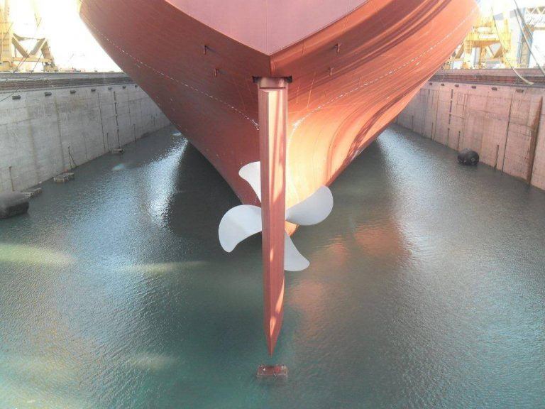
Five-blade propeller
A 5-blade propeller has the following properties:
- Vibration is the most minimum compared to all the other types of propeller.
- Manufacturing cost is more leading of all.
- Five-blade propellers have greater holding power in rough seas.
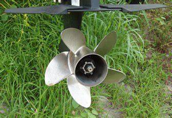
Six-Blade Propeller
Six-blade propellers have the following characteristics:
- Manufacturing cost is relatively high
- Vibration is the most minimum compared to all the other types of propeller.
- Six-blade propellers have greater holding power in rough seas.
- With a six-blade propeller, the produced pressure field over the propeller reduces
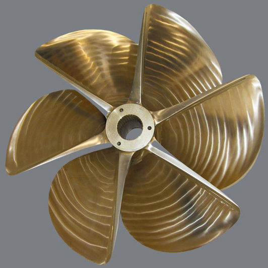
Classification by Pitch of The Blade
The pitch of a propeller can be described as the displacement that a propeller performs for every full revolution of 360 ̊. The organization of the propellers based on the pitch is as follows:
Fixed Pitch Propeller
The blades in the fixed pitch propeller are permanently connected to the hub. The fixed pitch type propellers are cast, and the position of the blades and the pitch position is always fixed and cannot be adjusted during the operation. They are typically made from copper alloy.
Fixed pitch propellers are reliable and robust as the system doesn’t include any hydraulic and mechanical connection as in Controlled Pitch Propeller (CPP). The manufacturing, operational, and installation costs are lower than the CPP type. The maneuverability of the fixed-pitch propeller is also not as great as CPP.
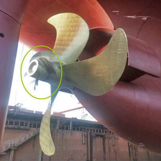
Controllable Pitch Propeller
In a Controlled Pitch type propeller, it is possible to adjust the pitch by rotating the blade about its vertical axis utilizing mechanical and hydraulic arrangement. This helps drive machinery at constant load with no reversing mechanism needed as the pitch can be modified to match the expected operating condition. Thus, the maneuverability enhances, and the engine efficiency also rises.
This disadvantage includes the probability of oil pollution as the hydraulic oil in the boss, which is utilized for regulating the pitch, may leak out. It is a complicated and costly system from both the establishment and operational point. Moreover, the pitch can get held in one position, making it difficult to maneuver the engine.
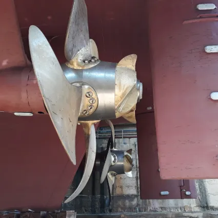
Nevertheless, the CP propeller’s propeller efficiency is somewhat lower than the same size FP propeller due to the immense hub to accommodate the blade pitch mechanism and piping.
Propeller Theory
Propeller theory is the physics governing the design of effective propellers. A propeller is the most popular propulsor on ships and small aircraft.
Theory of Operation
A propeller gives momentum to a fluid, which creates a force to act on the ship. The theoretical efficiency of any propulsor is that of an actuator disc in a perfect fluid. This is termed the Froude efficiency and is a natural limit that any device cannot exceed, no matter how great it is. Any propulsor with virtually zero slip in the water, whether this is a vast propeller or a large drag device, approximates 100% Froude efficiency.
The actuator-disc theory’s essence is that if the slip is defined as the ratio of fluid velocity raise through the disc to vehicle velocity, the Froude efficiency is equal to 1/(slip + 1). Therefore, a mildly loaded propeller with a large swept area can have a high Froude efficiency.
A real propeller has blades made up of parts of helicoidal surfaces, which can be thought to ‘screw’ through the fluid. Truly the blades are twisted airfoils or hydrofoils, and each part contributes to the total thrust. Two to six blades are most prevalent, although designs that are designed to operate at diminished noise will have further blades, and one-bladed ones with a counterweight have also been employed.
Slightingly loaded propellers for light aircraft and human-powered boats regularly have two blades. Motorboats regularly have three blades. The blades are connected to a boss (hub), which should be as tiny as the requirements of strength allow, with fixed-pitch propellers, the blades and boss are normally a single casting.
Cavitation
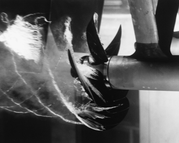
Cavitation creates vapor bubbles in the water near a moving propeller blade in zones of low pressure due to Bernoulli’s principle. It can happen if an effort is made to carry too much power through the screw or if the propeller is working at a very high speed. Cavitation can lose power, create vibration and wear, and create damage to the propeller. It can happen in many ways on a propeller. The two most prevalent types of propeller cavitation are suction side surface cavitation and tip vortex cavitation.
Suction side surface cavitation happens when the propeller runs at high rotational speeds or under heavy load. The pressure on the blade upstream surface can fall below the vapor pressure of the water, following in the formation of a vapor pocket. Under such circumstances, the variation in pressure between the blade’s downstream surface (the “pressure side”) and the suction side is restricted and ultimately diminished as the extent of cavitation is developed.
When most of the blade surface is coated by cavitation, the pressure difference between the pressure side and suction side of the blade loses considerably, as does the propeller’s thrust, which is called “thrust breakdown”. Operating the propeller under these conditions ruins energy and creates considerable noise. As the vapor bubbles collapse immediately erode the screw’s surface due to localized shock waves against the blade surface.
Tip vortex cavitation is created by the shallow pressures developed at the core of the tip vortex. The tip vortex is created by fluid wrapping around the propeller’s tip, from the pressure side to the suction side. This video shows tip vortex cavitation. Tip vortex cavitation typically happens before suction side surface cavitation. It is less damaging to the blade because this type of cavitation doesn’t fall on the blade but some way downstream.
How Does Propeller Work?
As we discussed earlier, the initial airplane propellers performed more like screws. It took the Wright Brothers’ ingenuity to develop a propeller that performed not like a screw but like a twisted airplane wing. Rather than creating a high/low air pressure differential to produce lift along a vertical axis, a propeller establishes a pressure differential to generate forward thrust along a horizontal axis.
Think about it this form: when you toss a paper airplane, it will create a small bit of lift before ultimately settling on the ground – presented you folded the paper right. The paper plane took flight since the wing’s design worked in tandem with the force you employed. Now presume if you could catch the plane in mid-flight and immediately re-throw it to stretch its travel. Then re-throw it again and again.
In the same way, a few thousand times a minute. That’s really what happens in a propeller system. The rotating blades work as an infinite series of running wings that continually force fluid rearward.
Things get a little more complex as we progress beyond that fundamental explanation of how propeller systems work. Many factors determine how effective a types of propeller system will be, including the blade pitch, the number of propeller blades, engine torque, and a propeller’s revolutions’ speed. Understanding these variables (and many others) allows aeronautical engineers to design propeller systems uniquely adapted to different applications.
Check out this amazing video about how various types of propeller systems work.
As you would imagine, choosing the correct propeller is a critical step in building a safe, efficient system.
Download Types of Propellers PDF
This document is also available in PDF format for your convenience. Download the file by clicking the link below.
Read More In linquip
- Types of Wind Turbines: The Quick and Easy Intro
- Types of Turbines: Classifications and Types
- Top 10 Steam Turbine Manufacturers in World (2022 Update)
- What is Mixed Flow Turbine? Basics, Advantages, and Applications
- What is Low Head Turbines?
- Radial Flow Turbine
- What is Tesla Turbine and How Does it Works?
- Hydrogen Gas Turbine: All You Need to Know
- Axial Flow Turbines and Working Principles
- What is Hydrokinetic Turbines? Working Principles and Output Power
- What is Propeller Turbine? Types and Working Principles
- What is Turgo Turbine and How does it Work?
- Differences between Pelton, Francis, and Kaplan Turbine
- Pelton Wheel | Parts, Types, Working Principle and Efficiency
- What is Kaplan Turbine? Diagram and Working Principles
- Impulse Turbine: Working Principle, Components, and Types
- Cross-Flow Turbine: Working Principle, Components, and Advantages
- An Ultimate Guide to Francis Turbine



would the pros and cons for the types of propellers still apply for aircraft.