Types of shaft couplings have different designs and working principles each one has its own characteristics and certain applications to serve. In the following section, we will explain the various types of shaft couplings in detail. Follow us in Linquip.
Linquip is the place where you can find all the information you need about couplings. You can get in touch with our experts if you have any questions about shaft couplings. If you would like a basic understanding of these devices, you may be interested to read Linquip’s article entitled “What Is Industrial Coupling?“.
Have you ever used one of these devices? Linquip’s selection of Coupling Products will help you find the coupling you are looking for. Do you have a specific type of shaft coupling in mind? Linquip offers free access to all available Coupling Devices for Sale online. If you are looking for shaft coupling prices, you can also use Linquip as a tool to submit an inquiry or request quotes from all Coupling Suppliers and Companies for free.
What is Shaft Coupling?
Couplings are mechanical elements that connect two drive elements, allowing the motion from one to the other. Shafts are commonly used as drive components. So, a shaft coupling is a mechanical feature that connects two shafts to transfer torque from one end to the other while accepting misalignment. Shaft couplings add mechanical stability, allowing for shaft misalignment tolerability. As a result of this coupling stability, irregular bearing wear, machinery vibration, and other mechanical issues caused by misalignment may be reduced. As a consequence of this coupling stability, irregular bearing wear, machinery vibration, and other mechanical problems caused by misalignment may be reduced.
Even where the motor and workpiece are closely attached and properly secured, minor misalignments may occur over time due to temperature fluctuations and changes in time, resulting in vibration and damage. Shaft couplings play an important role in reducing shock and vibration and allowing for smooth rotation. In a broader sense, shaft coupling may also refer to a mechanical system that connects neighboring sections or ends of objects.
Shaft couplings, in general, do not allow the shaft to be disconnected when in use, but there are torque restricting torques that can slip or detach if any torque reaches the limit. Shaft coupling selection, installation, and repair will minimize maintenance time and costs. Both couplings have the same basic function: to transfer power, tolerate misalignment, and compensate for axial movement (end movement of shafts).
Shaft couplings are mostly used for four purposes: (1) power transmission, (2) joining misaligned shafts, (3) reducing shocks and friction, and (4) being easily assembled and disengaged. There also various types of shaft couplings. Let’s learn them in the next section.
Types of Shaft Couplings
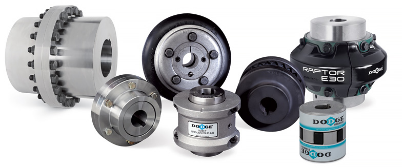
There are several types of shaft couplings available depending on the application such as: Beam, Bellows, Chain, Jaw, Diaphragm, Disc, Grid, Oldham, Schmidt, and Clamping. Let’s read more about them:
Beam Couplings
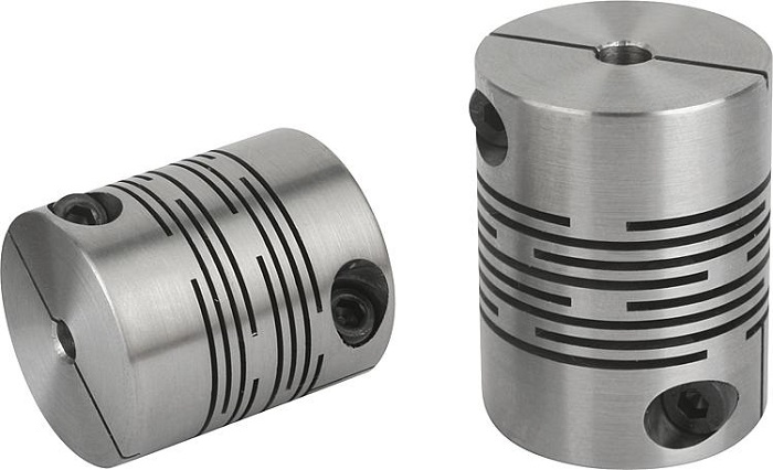
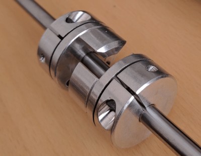
This coupling is one of the types of shaft couplings. The beam coupling is made up of a single or several helical cuts in the coupling body and can accept parallel misalignments of up to 0.025 inches and angular misalignments of up to 7 degrees. They are mainly used in motion control applications for torques of less than 100 inch-lbs. There are zero-backlash designs available to ensure precise positioning of the driving and guiding shafts.
Bellows Couplings
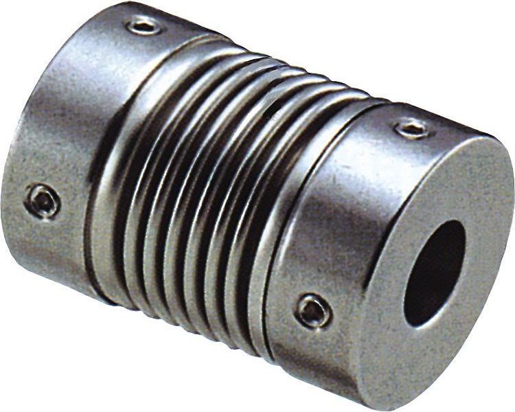
Bellows couplings are also appropriate for motion control applications. They are made up of multiple metal convolutions that provide high torsional stiffness, which is critical in positioning applications. Torsional stiffness limits the amount of angular and parallel misalignment they can tolerate as compared to beam couplings, though torque transmitting capacities are roughly comparable.
Chain Couplings
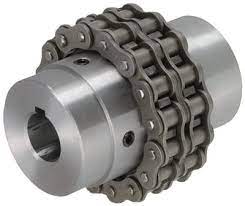
Chain couplings are designed for power transmission applications and can transfer power up to hundreds of horsepower. Misalignment allowances for angular and parallel misalignment are usually 2 degrees and 0.015 inches, respectively. Typical chain couplings employ special chain sprockets and double large roller chains, the clearances of which enable the design to function as a flexible coupling.
Jaw Couplings
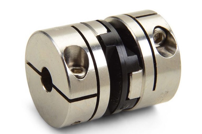
Next to the above types of shaft couplings, Jaw couplings are another type. Curved and straight jaw couplings, which are made up of pairs of multi-jawed hubs that mate with elastomeric spiders, are used for both motion modulation and light power transfer applications. Backlash-free torque transfer is possible thanks to the specification. Accommodation for parallel misalignment is usually less than 0.01 inches, and angular misalignment is less than 1 degree. Elastomeric spiders have damping power to these couplings, and the spiders are often available in various durometers to lend particular properties to the individual couplings. These couplings often work without lubrication and can convey torques of up to 1000-inch pounds.
Diaphragm Couplings
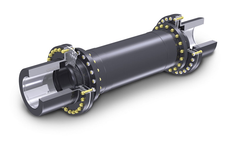
Diaphragm couplings are often used in high-power transmission applications such as turbomachinery. They usually use one or more flexible metal convoluted disks to transfer power to an inner spacer shaft and then back out to the powered machinery by another diaphragm stack. The lack of lubrication criteria is a significant improvement over gear form couplings. Diaphragm couplings can transmit high torque and operate at high speeds.
Disc Couplings
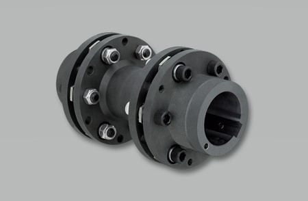
There more are types of shaft couplings. Disc couplings have one or more disks and one or two steps that bolt to the shaft hubs. They are power transmission devices that rely on the stability of their thin metal disks to transfer torque and tolerate angular misalignment. They are not very adept at dealing with parallel misalignment. They can transfer high torques and are often used to pair high horsepower engines, gas turbines, and so on to loads.
Grid Couplings
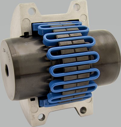
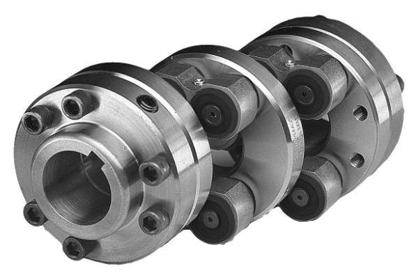
Grid couplings make use of spring-like binding elements that weave into slots machined into the coupling hubs. They can transmit high torque while also providing shock absorption and torsional vibration dampening. They may not need any lubricant to work. They are suitable for power transmission and can withstand parallel misalignment of up to 0.30 inches and angular misalignment of approximately 14 degrees.
Oldham Couplings
Because of their sliding element configuration, Oldham couplings can accommodate high degrees of parallel misalignment. In current models, an elastomer core part is used instead of metal. Some manufactures say that by using cylindrical sliders rather than rectangular sliders, they can withstand up to a 5-degree angular misalignment.
Schmidt Couplings
Schmidt couplings are uniquely engineered to work on offset shafts. They are not, strictly speaking, adjustable couplings, which are constructed to tolerate minor misalignment in shafts that are theoretically parallel and square to one another. Schmidt couplings, which behave more like a 1:1 gearbox in a smaller vacuum, are used in papermaking, printing, and related devices.
Clamping Couplings
Rigid one- and two-piece Clamping couplings lack shaft misalignment accommodation and are common for sluggish or irregular shafting arrangements where alignment is not an issue. They are the most basic form of shaft coupling and, except for their lack of misalignment resistance, are low-cost zero-backlash systems.
What Is the Material That Is Used for Couplings?
Aluminum alloys and stainless steel are the most common materials used for these products, but they can also be produced from acetal, maraging steel, and titanium.
We have discussed what shaft coupling is as well as the purpose. We also explained different types of shaft couplings. Each of these couplings has benefits and uses, so it is necessary to have in-depth knowledge about each one if you have to prolong the life of your machine as much as possible. These were basic descriptions of the main types of shaft couplings that you are most likely to use.
Download Types of Shaft Couplings PDF
It is also possible to download a PDF version of this document directly to your computer if you prefer. Just click on the following link to download the PDF file.
We hope we helped you shed a little light on this topic and inspired you to keep learning. If you want to find out more about a specific one, or if you are not sure about the type of shaft coupling you need and which solution would be the best, it is better to consult an expert who can help you. Let us know in the comment section by registering in Linquip. We will respond to you.
Read More In Linquip
- Flange Coupling Adaptor: Working Principle and Applications
- What is Sleeve Coupling? Ultimate Guide 2022
- What is Jaw Coupling? Working Principle & Size Chart
- What Is a Fluid Coupling? Diagram + Parts
- What is Disc Coupling: A Complete Guide
- What is Grid Coupling? Essential Details You Need To Know
- A Cheat Sheet For The Types of Pump Couplings
- Advanced Guide: Types of Rigid Couplings
- The Quick Guide To The Types of PVC Couplings
- The Complete Library of Types of Flexible Coupling
- The Practical Guide To Types of Coupling in 2022
- Types of Gear Coupling: a Basic Yet Crucial Description of the Types



I’m building a swing blade sawmill. I’m intending to use jaw coupling to connect the gearbox to the saw shaft. There is no angular misalignment but an approximate one millimetre misalignment between the two shafts. The speed is 2700 rpm and the power is 25 up. I wonder if I do the right thing.
Thanks for visiting our website, Paul! You can visit our Expert page, where you can ask your questions from thousands of our experts and solve your issue through this process.