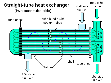
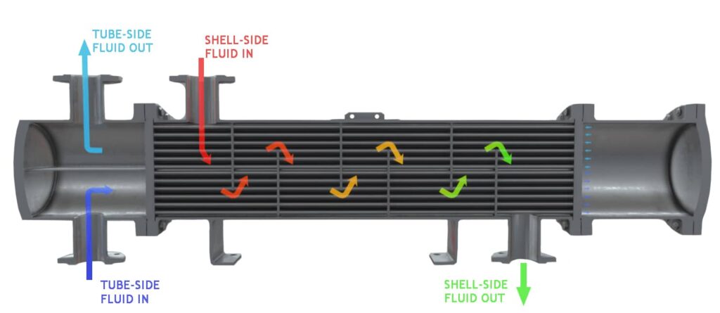
In general, there are two available types of shell and tube heat exchangers, each of which is suitable for the industry in which it is used: one is shell and tube heat exchangers that are used in the petrochemical industry and follow TEMA (Tubular Exchanger Manufacturers Association) standards; Another is those used in the heating industry, such as heat exchangers used in feedwater heating or condensers in thermal power plants.
One of the most popular heat exchanger types is shell and tube heat exchangers, which are used in a wide range of pressure and temperature due to their capacity. Simply put, a shell and tube heat exchanger is a device that uses tubes inside an outer cylindrical shell to create a thermal contact between two working fluids. These two integral paths are usually made of thermally conductive metals (steel, aluminum alloys, etc.) that allow easy heat transfer.
One of the working fluids passes from the inlet of the tubes to their outlet on the tube side, while on the shell side, a separate fluid passes over the tubes. The number of tubes in a tube bundle determines how much surface area is provided to the shell-side flow and thus how much heat is transferred. These devices are among the most effective heat exchange tools because they perform excellent heat transfer and are compact and easy to build and maintain. They are widely used in industries such as condensers, evaporators, turbine coolers, feedwater preheating, etc.
Parts of a Shell and Tube Heat Exchanger
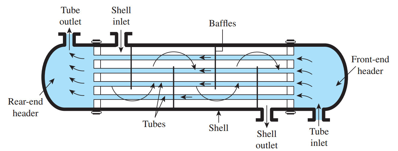
Changes in the main components of the structure make different types of shell and tube heat exchangers. Regardless of the industry in which this heat exchanger is used, a shell and tube heat exchanger is created from the following main components.
Tube Bundle
This set consists of the tubes, tube sheets, baffles, and tie rods to retain the bundle together.
Shell
The shell contains a tube bundle; one of the working fluids flows in the shell over the tubes.
Front Header
The front header also called the stationary header, is where the fluid enters the tube side of the exchanger.
Rear Header
The rear header is where the tube side fluid leaves the heat exchanger or in heat exchangers with multiple tube side passes, where it is returned to the front header.
Geometric Terminology of Shell and Tube Heat Exchanger
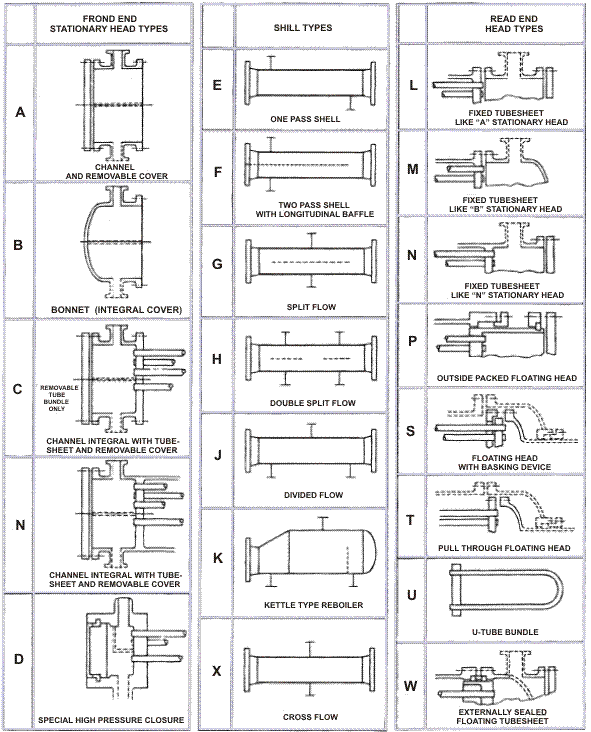
As the shell and tube heat exchangers are common, a standard nomenclature is developed for their designation and used by the TEMA. This nomenclature is set based on letters and diagrams. The first letter explains the front header type, the second one describes the shell type, and the third one represents the rear header type. The full TEMA nomenclature is shown in the following figure.
Main Types of Shell and Tube Heat Exchanger
Many arrangements of the front header, shell, and rear header can be considered. Three main combinations are presented here.
Fixed Tube Sheet Heat Exchanger
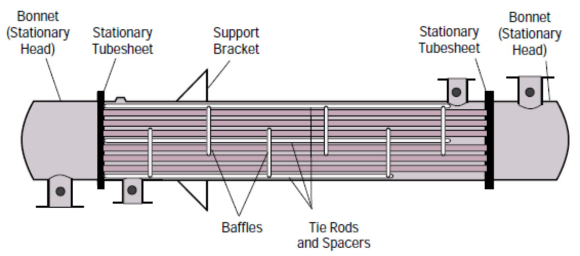
In this type of exchanger, the tube sheet is welded to the shell. This leads to a simple and economical structure, and the cleaning of tube bores can be performed mechanically or chemically. However, the outer surface of the tubes is inaccessible other than chemical cleaning. Rear headers are usually of L, M, and N types.
Suppose there is a large temperature difference between the shell and tube materials. In that case, it may be necessary to form an expansion bellows in the shell, to remove excessive stresses caused by expansion. Such bellows are usually the cause of weakness and failure in work. In cases where the failure is severe, other unit types are normally used.
This is the cheapest design of all removable bundle ones but is generally somewhat more expensive than a fixed tube sheet at low pressures.
U- Tube Heat Exchanger
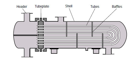
In a U-Tube exchanger, any type of front header may be used, and the rear header is typically M-Type. U-tubes allow unlimited thermal expansion. Also, the tube bundle can be eliminated for cleaning, and a small bundle to shell clearances can be obtained. Since it is difficult to clean inside the tubes with mechanical tools, it is normal to use this type only where the fluids on the tube side are clean.
Floating Head Heat Exchanger
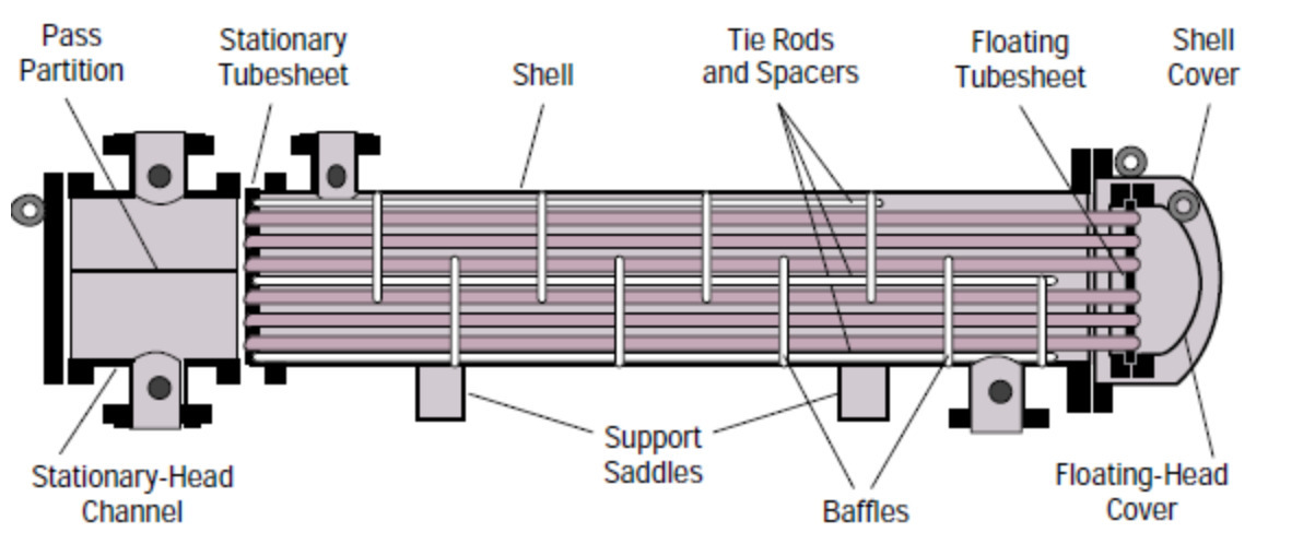
In the floating head exchanger, the tube sheet is not welded to the shell at the rear header end but is permitted to move or float. The tube sheet at the front header (fluid inlet end on the tube side) has a larger diameter than the shell and is sealed in a manner similar to that applied in the fixed tube sheet design. The tube sheet at the rear header end of the shell is somewhat smaller in diameter than the shell and allows the bundle to be drawn through the shell.
The application of a floating head means that thermal expansion is allowed, and the tube bundle can be eliminated for cleaning purposes. Several types of rear headers can be utilized, but the S-Type Rear Head is the most common. The floating head heat exchanger is suitable for performing the precise services related to high temperatures and pressures but is more expensive than the equivalent fixed tube sheet exchanger (typically 25% for carbon steel construction).
Types of Shell and Tube Heat Exchanger Parts
There are various types of headers, shells, and baffles explained briefly below.
Front Header Types
Front headers include A, B, C, D, N, and Y types.
The A-type front header allows access to the tubes for cleaning or repairing purposes without disturbing the pipework. It is easy to fix and replace. However, the risk of leakage and the header cost is higher than the B-type header.
B-type is the cheapest front header type. Compared to A-type, it is more suitable for higher pressures. A drawback of the B-type front header is that gaining access to the tubes leads to disturbance to the pipework to remove the header.
The C-type header is suitable for high-pressure applications (more than 100 bar). It allows access to the tube without disturbing the pipework. However, repair and replacement are difficult.
The D-type front header is the most expensive type. The use of this type is very high-pressure cases (more than 150 bar). It permits access to the tubes without disturbing the pipework. In this type, it is challenging to repair and replace.
The N-type header provides access to the tubes without disturbing the pipework. In addition, it is cheaper than the A-type. However, the problem of difficulty of maintenance and replacement still exists.
Y-type can be utilized as a front or rear header and is applied when the exchanger is used in a pipeline. It is the cheapest type of header, which reduces piping costs. Although it is principally used with single-tube pass units, any odd number of passes can be allowed with appropriate partitioning.
Rear Header Types
Rear headers include L, M, N, P, S, T, U, and W types.
The L-type rear header is only for applications on fixed tube sheets since the tube sheet is welded to the shell, and it is not possible to have access to the outside of the tubes. The principal advantage of the L-type rear header is that access can be obtained to the inside of the tubes without the need to remove pipework. However, the main drawback is that an expansion roll is required to allow large thermal expansions, limiting the allowed working temperature and pressure.
The M-type header is a similar header to the L-type rear header but slightly cheaper. However, it must be removed to obtain access to the inside of the tubes.
The advantage of the N-type rear header type is that the tubes can be accessed with no disturbing pipework. However, N-type headers are difficult to repair and replace.
The P-type header is a cheap floating header allowing access to the inside of the tubes to be cleaned. For this target, it enables the bundle to be removed for cleaning. However, it is appropriate for low pressures and non-hazardous fluids, and small thermal expansions.
S-type is the most expensive floating headers type. However, its benefit is that the bundle can be removed, and limitless thermal expansion is possible.
T-type is cheaper and easier for the bundle to be removed than the S-type but allows unlimited thermal expansion.
U-tube is the cheapest removable bundle design but slightly more costly than a fixed tube sheet at low pressures. However, it allows unlimited thermal expansion and bundle removal to clean the outside of the tubes. U-tube design is limited to even tube pass numbers.
The W-type rear header is the cheapest floating header, allowing unlimited thermal expansion and tube bundle removal for cleaning. The limitation to low-pressure nonhazardous fluids is a problem in this header type.
Shell Types
Types of the shell are E, F, G, H, J, K, and X-types.
The most common type of shells is E-type, well-suited for most applications. F-type is suitable when pure counter flows are needed at two tube sides. G-type is used for cases with small pressure drop at the shell side. H-type is similar to F-type but in larger units.
J-type shell is usually used in cases where the maximum allowable pressure drop is greater than that with an E-Type shell. It is also utilized when tube vibration is a problem. K-type is employed only for reboilers to supply a large disengagement space to minimize shell-side fluid carryover. X-type is appropriate when the maximum shell side pressure drop is exceeded by all combinations of other shell types.
Baffle Types
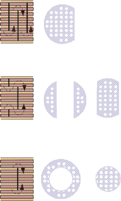
Baffles direct flow through the shell side to increase the effective heat transfer due to greater turbulence. They also help support the tubes from vibration damages. Baffles are connected to the tube bundle instead of the shell so that the bundle can still be removable for maintenance.
Three main types of baffles are single segmental, double segmental, and disk and doughnut, depicted in the following figure, respectively.
Types of Shell and Tube Heat Exchanger Design
There are many variations of the shell and tube design.
U-tube Heat Exchanger
In general, the ends of each tube are joined to plenums (sometimes called water boxes) by holes in tube sheets. The tubes can be straight or bent U-shaped, like two-phase steam generators in nuclear power plants.
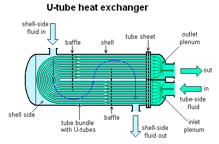
Most shell and tube heat exchangers have either 1, 2, or 4 passages on the tube side. These numbers refer to the times the fluid in the tubes passes through the shell.
Straight Tube Heat Exchanger
Surface condensers in power plants are usually from the type of single-pass straight tube heat exchangers.
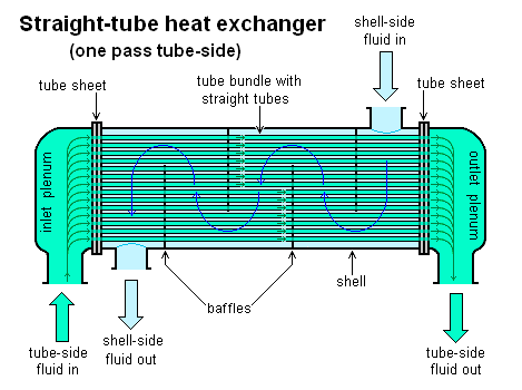
In two and four pass designs, the fluid can enter and leave on the same side, making the structure simpler.
