As you may know, inductors are passive two-terminal electrical components consisting of an insulated wire wound into a coil around a core. There are different types of inductors used in the industry. Each of these different types has some special uses and applications. In this article, we will take a closer look at different types of inductors. Read this new blog on Linquip to find out more about each type.
Different Types of Inductors
Based On Core Material
- Air Core Inductor
- Iron Core Inductor
- Ferrite Core Inductor
- Laminated Steel Core Inductor
- Iron Powder Core Inductor
- Ceramic Core Inductor
Based On Core Design
- Toroidal Core Inductor
- Bobbin Core Inductor
Based on Their Usage
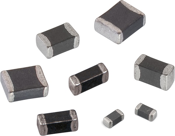
- Multi-Layer Inductor
- Thin Film Inductor
- Molded Inductor
- Coupled Inductor
- Power Inductor
- Radio-Frequency RF Inductor
- Chokes
- Variable Inductor
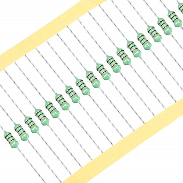
- Colour ring inductor
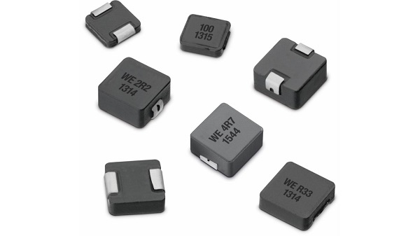
- Shielded Surface Mount Inductor
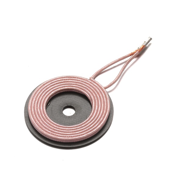
- Wireless Charging coils
There are many different types of inductors available based on the specific materials, core design, and usages. Each one has certain benefits and trade-offs that must be considered when tailoring to the specific application intended.
Types Of Inductors Based On Their Core
The Core of the Inductor is its heart. There are many types of Inductors according to the core material used. Let us have a look at a few of them.
Air Core Inductor
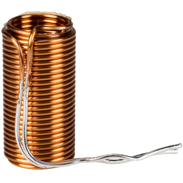
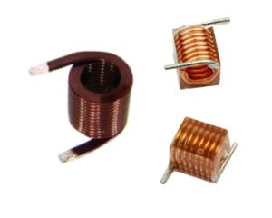
The commonly seen inductor, with a simple winding, is this Air-Core Inductor. This has nothing but air as the core material. Air core inductor uses any non-magnetic material like plastic and ceramic as core to reduce the core losses i.e. eddy current and stray losses, especially when the operating frequency is very high. However, the use of a non-magnetic core also decreases its inductance.
Air Core Inductors are used for constructing RF tuning coils. They are also used in filter circuits, snubber circuits, and high-frequency applications including TV and radio receivers.
Iron Core Inductor
These Inductors have Ferromagnetic materials, such as ferrite or iron, as the core material. The usage of such core materials helps in the increase of inductance, due to their high magnetic permeability. These inductors have high power value but are limited in high-frequency capacity.
The inductors that have ferromagnetic core materials just like these suffer from core losses and energy losses at high frequencies.
In the areas where low space inductors are in need then these iron core inductors are the best option. These Inductors are also used in the manufacture of a few types of transformers. Iron core inductors are applicable in audio equipment. When compared with other core indicators these have very limited applications.
Ferrite Core Inductor
These types of inductors use ferrite cores. Ferrite is a material with high magnetic permeability made from the mixture of iron oxide (ferric oxide, Fe2O3) and a small percentage of other metals such as nickel, zinc, barium, etc.
The ferrite core has very low electrical conductivity which reduces the eddy current in the core, resulting in very low eddy current loss at high frequency. Hence they can be used in high-frequency applications. They also offer advantages of decreased cost.
There are two types of ferrites i.e. Hard Ferrites and Soft Ferrites.
The Hard ferrites are also called permanent magnets. These will keep the polarity of the magnetization even after removing the magnetic field. They are not used in inductors because of their high hysteresis loss.
The Soft ferrites can reverse the polarity of their magnetization without any particular amount of energy needed to reverse the magnetic polarity. Their magnetization changes easily and are good conductors of the magnetic field. Thus they are used in transformers and inductors.
Laminated Steel Core Inductor
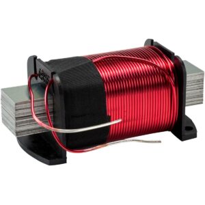
In such types of inductors, the core is laminated which means that it is made up of a bunch of thin sheets placed on top of each other in a tight form. The sheets are coated with insulation to increase their electrical resistance and prevent eddy current flow between them. Therefore the eddy current loss in laminated core inductors decreases significantly. They are used in high-power applications.
Iron Powder Core Inductor
These are formed from very fine particles with insulated particles of highly pure iron powder. This type of inductor contains nearly 100% iron only. It gives us a solid-looking core when this iron power is compressed under very high pressure and mixed with a binder such as epoxy or phenolic. By this action iron powder forms like a magnetic solid structure which consists of a distributed air gap.
Due to this air gap, it is capable of storing high magnetic flux when compared with the ferrite core. This characteristic allows a higher DC level to flow through the inductor before the inductor saturates. This leads to the reduced permeability of the core.
Mostly the initial permeability is below 100 only. Thus these inductors possess high-temperature coefficient stability. These are mainly applicable in switching power supplies.
Ceramic Core Inductor
Ceramic is a non-magnetic material just like air. Ceramic cores are used to provide a shape for the coil and a structure for its terminals to sit upon. As it is a non-magnetic material, it has low magnetic permeability and low inductance. But it provides a reduction in the core losses. It is mostly available in SMD packaging and is used in applications where low core losses, High Q, and low inductance are required.
Types Of Inductors Based On Core Design
The geometry of the core also plays a role in the inductor’s performance. Some of these designs are given below.
Toroidal Core Inductor
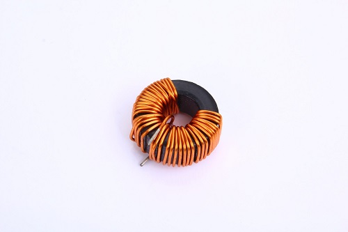
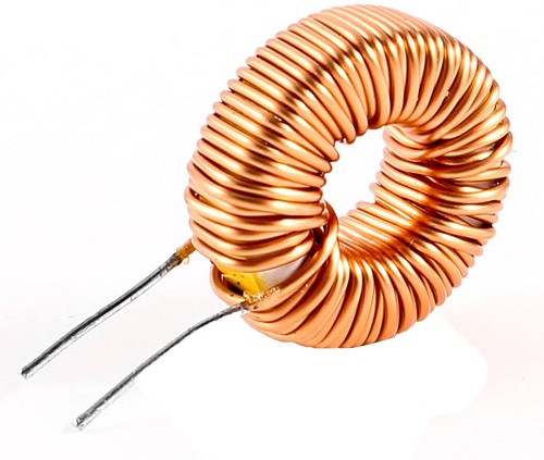
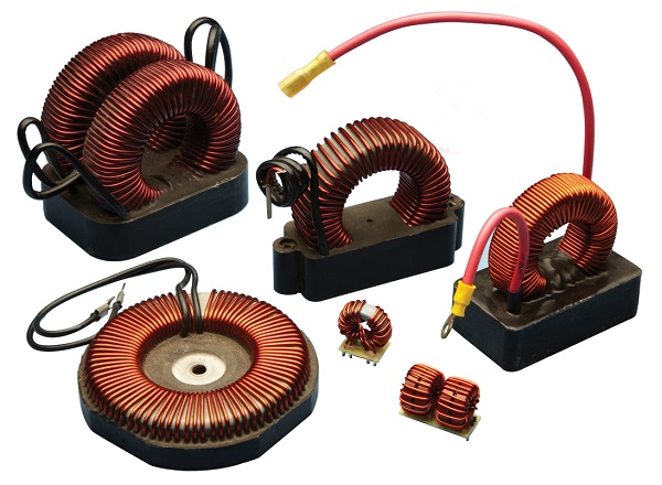
The construction of an aToroidal core inductor includes a wire wrapped around the core which has a ring or donut-shaped surface. These are generally made up of different materials like ferrite, powdered iron and tape wound, etc. This inductor has high coupling results between winding and early saturation.
Its arrangement gives the minimum loss in magnetic flux which helps to avoid coupling magnetic flux with other devices. It has high energy transferring efficiency and high inductance values at low-frequency applications. These inductors are mainly used in medical devices, switching regulators, air conditioners, refrigerators, telecommunications, and musical instruments, etc.
Bobbin Core Inductor
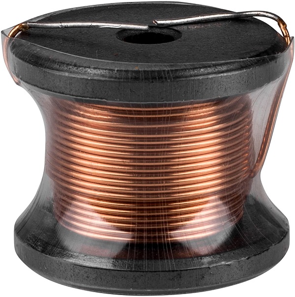
The bobbin core inductor is made of a bobbin-shaped core. It is a cylinder with two flat discs at each end. It is also known as the drum core inductor.
The coil is wrapped around the cylinder. The bobbin core does not provide a closed magnetic path; instead, the flux goes through the disc into the air gap and then enters the core through the second disc at the other end. It provides a large air gap for its magnetic field to store more energy, which increases the inductor’s saturation current. This means that the inductor can withstand high peak currents without saturation but at the cost of electromagnetic interference (EMI) radiation.
Types Of Inductors Based on Their Usage
Inductors are designed for different usage. Their design varies from application to application where some of these inductors based on their usage are given below.
Multi-Layer Inductor
As the name suggests, these inductors have multiple layers of wire wound on top of each other. Such inductors have large inductance due to an increase in the number of turns of the winding.
In these multilayer inductors, not only does the inductance of the inductor increase but also the capacitance between the wires also increases. The biggest advantage of these inductors is that by giving the lower operating frequencies, we can get higher inductance results.
These types are applied at high frequencies to suppress noise, in signal processing modules like wireless LANs, Bluetooth, etc. They are also used in mobile communication systems.
Thin Film Inductor
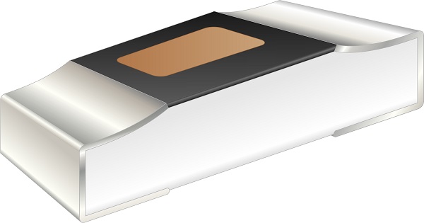
Such type of inductor is designed on a substrate of thin ferrite or magnetic material. A conductive spiral-shaped trace of copper is placed on top of the substrate. The design allows stability and resistance to vibrations.
Due to its high accuracy, performance, and compact size, it is used in mobile communication devices, wireless networks and power supplies, etc.
Molded Inductor
Such inductors are coated with insulation such as molded plastic or ceramics just like the resistors. The core is made from ferrite or phenolic material. The winding can be in different designs and it is available in different shapes like axial, cylindrical, and bar shapes.
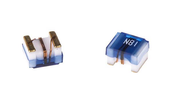
The Molded inductors are available in SMD and THT as well. Their miniature size and light weight allow them to be used in PCB (Printed circuit boards), mobile devices and computers, etc.
Coupled Inductor
Couple inductors are made of two windings around a common core. The changing magnetic flux due to the first winding induces EMF in the second winding; this phenomenon is known as mutual inductance. These both winding are electrically isolated. Thus a coupled inductor provides electrical isolation between two circuits. A Transformer is a coupled inductor.
They have multiple applications depending on their winding. 1:1 winding ratio inductors are mostly used for electrical isolation or increasing the series inductance. The winding ratio of 1: N coupled inductors (which can step up or step down voltages) are used in other energy conversion circuits such as flyback, SEPIC, ZETA, etc.
Power Inductor
These inductors are specifically designed to withstand high currents without reaching the magnetic saturation region. To increase the saturation current rating, the inductor’s magnetic field is increased, which causes EMI (Electromagnetic interference). To reduce the EMI, most power inductors are used with proper shielding. They are available from a few amps to a few hundred amps in both SMD and through-hole packaging.
Radio-Frequency RF Inductor
Such types of inductors are designed for high-frequency applications. A general inductor does not perform very well due to its high impedance and core losses at high frequency. Most of these losses occur due to parasitic capacitance, skin effect, proximity effect, and eddy current loss, etc. The eddy current loss is directly proportional to the frequency. Thus it is eliminated by entirely removing the core, instead of using an air-core inductor.
While the parasitic capacitance is caused due to the potential difference between the turns of winding that are at proximity. It causes the inductor to self-resonate at a high frequency. It is reduced by maintaining some space between the wires and wounding the coil in a spider web or basket weave (honeycomb) design to avoid parallel turns.
Chokes
Choke is just a simple inductor but it is specifically designed for blocking (choking) high-frequency signals. The impedance of a choke increases significantly with the increase in frequency. Therefore, it blocks high AC and allows DC and low-frequency AC with some loss.
The Inductors that are used as chokes are constructed without using any of the impedance reduction techniques which are used to increase its Q-factor. The chokes have low Q-factor and it is designed this way deliberately because we want its impedance to increase by increasing the frequency.
There are two types of Chokes i.e. AF chokes and RF chokes. The AF (audio frequency) choke is used for blocking Audio frequency and only allowing DC. The RF (radio-frequency) chokes are designed to block RF frequency while allowing DC and audio frequency.
Variable Inductor
As the name suggests, these inductors are designed to have variable inductance. This variable inductor is designed in more than one possible way.
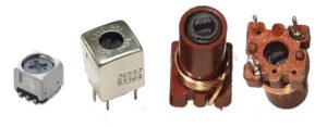
The most common design of variable inductors is having a movable ferrite core. Moving the core along the winding will increase or decrease the permeability which affects the inductance. The core can be designed to slide or screw in or out of the coil.
Another method of variable inductor design is to increase or decrease the number of turns through movable contact on top of the windings. The conductor used in these windings has no insulation (so the core must be insulated), thus moving the contact on top of the turn will change the number of effective turns. As the number of turns is directly proportional to the winding, the inductance varies accordingly.
Variable inductors are used in radio and high-frequency applications where tuning is required. These inductors are typically ranged from 10 μH to 100 μH and in present days these are ranged from 10nH to 100 mH.
Colour ring inductor
To make this type of inductor a very thin copper wire is wrapped around a dumbbell-shaped ferrite core, and two lids are connected at the top and the bottom of the dumbbell core. After that it goes through a molding process where the values are printed as colored bands, therefore, we can determine the value of the inductor just by reading the color bands and comparing them with the color code chart just like a resistor.
These types of inductors are used in the line filter, filter design, and boost converter.
Shielded Surface Mount Inductor
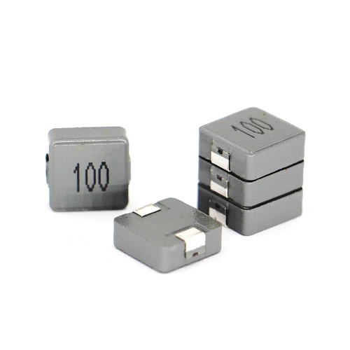
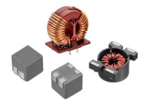
It is built by winding a length of wire in a cylindrical bobbin and securing it in a specially made ferrite housing forms, shielded surface mount inductor.
These inductors are specially designed for PCB mounted applications and the shielding is there to reduce EMI and noise from the inductor and also to be able to use in a high-density design.
Wireless Charging Coils
Coiling up a multi-stranded wire then putting it in a ferrite will result in a wireless charging coil. A length of multi-stranded wire is used to reduce the skin effect, which describes a high-frequency magnetic field that can penetrate a certain depth, which means if a solid wire is used in this case the most of the current will flow through the outer part of the conductor which therefore increases the resistance. By placing a ferrite plate under a coil it can improve the inductance and can also focus the magnetic field and reduces emissions.
wireless charging coils are used in wireless charging; information and communication products; industrial, medical, and other products.
As it can be seen, there are several ways to classify the different types of inductors. Each has its advantages, and it is, therefore, necessary to decide on the various options available when choosing an inductor for a particular application. Now that you know different inductor types, let us know what you think by leaving a reply in the comment section. We will be more than glad to have your viewpoint on the article. Is there any question we can help you through? Feel free to sign up on the Linquip website where our experts are prepared to provide you with the most professional advice.
Buy Equipment or Ask for a Service
By using Linquip RFQ Service, you can expect to receive quotations from various suppliers across multiple industries and regions.
Click Here to Request a Quotation From Suppliers and Service Providers
Read More In Linquip
- What is Inductor: Everything You Need to Know
- Difference between Capacitor and Inductor- Capacitor vs. Inductor

