Bevel gears are power transmission parts first employed to modify the direction of shaft rotation and reduce the speed and improve the torque between non-parallel spinning shafts. They are utilized on shafts with intersecting axes and, in particular, issues on shafts whose axes do not cut across. Shafts are always, but not presently, perpendicular. Essentially, bevel gears can be categorized by their tooth shape, either curved or straight. Bevel gears are explained here, along with a discussion of their performance and usual applications.
What is a Bevel Gear and How Does it Work?
Gears or cogwheels are instruments made of toothed wheels that transmit mechanical energy between two elements. They are typically employed in machines employed in multi-industrial processes, such as drive systems and production lines, but also in sections as diverse as aeronautics, mining, textiles, or pharmaceuticals. The aim for which they are constructed determines the model of the gears (bevel gears, spur gears, helical gears, etc.) as well as their substances.
The use of gears is widespread since they offer many benefits:
- They can transfer huge amounts of power
- They occupy a little place
- They need very simple maintenance
- They have a high performance
- They remove any chance of slippage
In this post, we will focus on what a bevel gear is and how it works to learn its features and understand how to choose the most suitable for the required project.
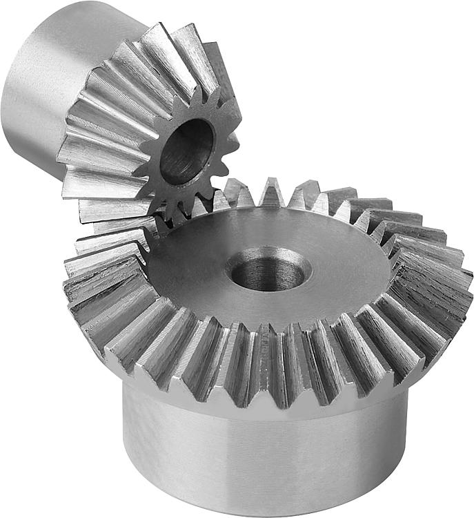
Bevel Gear Characteristics
Bevel gears are types that utilize two conical forms of toothed wheels to transmit energy between axes that are cut within the same space; however, hypoid gears can transmit energy between two axes that cross each other.
The teeth of a bevel gear can be either spiraled or straight, which is also introduced as a conical helix. Several kinds of gears can be classified not only based on the width of their tooth but also the tooth face width or the circular pitch of the center.
Straight Tooth Bevel Gears
The tooth form of a straight tooth bevel gear is functionally that of a spur gear but one whose geometry tapers toward the point of a conceptual shape. Both cones should meet at a common point for mating gears, and for this reason, bevel gears are not replaceable in the manner of spur gears. These conceptual cones are introduced as pitch cones. Another conceptual cone is the back cone, which describes the outermost edge of the tooth, the greatest part of the tooth where the shape and size are determined. Tooth faces commonly have a slight crown-like spur gear.
Sometimes gears of a 1:1 ratio are employed easily to modify the direction. These particular cases of bevel gears are named miter gears. Since each gear has an equal number of teeth, straight-tooth miter gears may be utilized as interchangeable pairs.
Curved Tooth Bevel Gears
Curved tooth bevel gears, occasionally introduced as helical bevel gears, are used with intersecting some shafts. The spiral tooth kind confers many of the identical improvements that helical gears have over spur gears: more tooth touching, larger high-speed potential, and quieter performance. Typically, they operate only in one direction. The common spiral angle for a spiral bevel gear is 35°.
Since meshing of the gear teeth occurs gradually, spiral bevel gears lend themselves to more appropriate adjustments than straight types, where tooth touching happens all at once across the face section of the tooth. With the development of CNC machining, spiral types have become much less expensive to create and so find benefits in several power-transmission applications where at one time, their usage would have been cost-preventative.
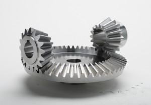
Hypoid gears are employed where the shafts are at best angles but do not cut across. Hypoid gears were produced to revise a problem with the rear-wheel type of drive automobiles. Using an intersecting shaft model produced a high entrance to the differential housing, which required considerable clearance in the drive-shaft tunnel. The mating point of the pinion and gear with a hypoid gear could be decreased, lessening the clearance required for the driveshaft to operate to the back of the car and allowing a shallower tunnel and roomier passenger compartment.
A particular case of the curved tooth type (and one not severely considered a helical bevel gear) is the Zerol type. It is named so because of having a zero spiral angle, and it can be replaced for straight tooth types without concern for inward thrust created by helical bevel gears. Also, unlike helical bevel gears, Zerol types can turn in either direction. Zerol types are used on intersecting shafts.
What is a Bevel Gear Used for?
Each kind of bevel gear is commonly employed in specific operations. If you want to know the different applications of bevel gears, click here.
Straight Bevel Gears
Even though they are somewhat nonuse when compared to other forms of gears, especially due to the noise that they produce during their performance, straight bevel gears still have several uses in dentist drills, watches, vending machines, and hand drills.
They are also still employed in certain conditions, such as in the handling of substances, etc. They are typically seen in lawn and garden equipment, food packaging and canning, machines such as mills and drills, compression systems for the oil and gas market, and flow control valves.
Spiral Bevel Gears
These gears have varied teeth. Bevel gears are utilized in conditions in which it is essential to invert the direction of shaft rotation. The teeth are designed to present a smoother meshing and greater tooth contact in spiral bevel gears when compared to a straight bevel gear. This decreases the noise and vibrations that commonly take place when gears like straight bevel gears and others move at great speeds.
Spiral bevel gears present a great level of monitoring over how teeth mesh, and their structure allows for special mounting deflections without extremely increasing the force on either end of the teeth. They can be employed at high velocities, and are typically used in bicycle and motorcycle gears.
Hypoid Gears
Hypoid gears are employed in many applications when speeds exceed 1,000 revolutions per minute. Regardless of this, they are beneficial for low-speed cases that need an extremely smooth motion or a silent performance.
Hypoid gears are often used in multistage gearboxes at the output stage, which needs higher torques and lower speeds. The most usual application of hypoid gearboxes is in the automotive industry, where they are employed in rear axles – particularly in big trucks.
Their angles – a left-hand spiral on the pinion and a right-hand spiral on the basic gear– allow for a movement “below the center.” This can allow for the driveshaft to be installed at the bottom, which leads to a smaller center of gravity for the system and does not influence the passenger compartment so much.
Applications of a Bevel Gear
Bevel gears see significant applications in construction equipment, automotive drivetrains, helicopter transmissions, marine thrusters, locomotives, etc. They are utilized in various industrial applications too, such as assembly-line transmissions, escalator drives, and wind-tower gearing, for instance. Even a single-hand drill uses a 90° form of bevel gear.
A normal rear-wheel drive differential will combine a ring gear and hypoid pinion as well as two pinions and two straight tooth bevel gears. Non-hypoid differentials are occasionally used in lower motion-control cases where the average velocity of two output shafts should always be at an equal ratio to the velocity of an input shaft.
Spiral bevel gears are being employed more in less-customary applications needing right-angle movement. Smaller elements are applied in many motion-control devices where tight backlash monitoring is essential. They can make the arrangement of components simpler as both output and input shafts are placed on the same surface, unlike cross-axis bevel gears where the two shafts exactly place on different surfaces.
Spiral bevel gears are thus becoming extremely usual in packaging devices and similar cases. They are purchased as commercial boxed sets with certain ratios of 1:1 and 2:1 usual and double-output shafts present with counter-rotating outputs are also feasible.
Considerable attention should be paid to the assembling of bevel gears to guarantee their rigidity. Gears supported on both sections are prepared to overhung gears, though, in some cases, these are unavoidable.
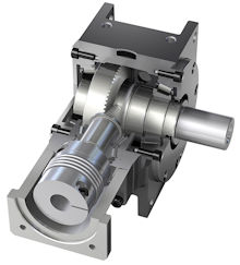
Worm gears present an alternative method of decreasing shaft velocities and rising torque through right angles, but their reduction levels are noticeably greater than bevel-gear reductions, and they typically create high heat/friction in their function. Information on these parts can be found in our comprehensive post on worm gears.
Gears are generally made from AGMA grade 20 cast iron, with greater grades accessible for increased strength at increased prices. Steel is always applied as a pinion substance meshing with a cast iron gear to give a more appropriate balance to component wear. Heat treating can twist gears, so it is commonly just used with gears constructed of alloy steels. Grinding after the heat process can upgrade tooth profiles. Bronze is employed to make gears better. Different plastics are also utilized to create gears, occasionally as the gear that mates with a steel or cast iron pinion.
What is a Bevel Gearbox?
There are many different types of the gearbox – or a gearhead, as some are desired – and the bevel gearbox is one of the most typically employed in power transmission and automation applications. The term indicates the gear within the gearbox – i.e. bevel gears – a simple unit that easily engages the beveled sides of two gears and transmits the rotation of one to the other, such as interlocking fingers.
Most bevel gears have a shape like a cone in their appearance – this is because the pitch surface of a gear is modeled to install at an angle met by a pairing gear, which runs the power at an angle from the source. If that angle is smaller than 90°, this cone-shaped gear – or acute model – is introduced as the external – since the teeth are facing outward. Anything with an obtuse angle – which means more than 90° – is introduced as an internal bevel gear. You can also have a crown type, which is where the angles of the pitch are precisely 90°, and the teeth are parallel to the main axis, resembling the points of a crown.
These bevel gearboxes, whichever of these existing types you’re looking at, are employed in a broad range of environments to transfer and/or split the energy of one rotating mechanical source through a specified angle. This angle is typically 90° but can change based on the requirements of the application in both obtuse and acute designs (greater or less than 90°).
The key advantage of a bevel gear over a worm gear used for the best angle transmission is the efficiency of the system. Worm gears are commonly only around 50-80% efficient, so 20-50% of the energy is wasted within the right-angle system. Bevel gearboxes, however, can be efficient up to 98% – with just a tiny waste of energy from input to output.
More about Bevel Gearboxes
Constructed and sold as a simple stage unit, bevel gearboxes are commonly presented with ratios between 1:1 to 5:1 – though they can also be provided in fractional gear levels, for example, 1:5:1 – it means that they are conformable to a broad range of applications and cases where this motion transfer is needed. Other forms of bevel gear can consist of Nidec Graessner’s hypoid spiral form, which allows a 15:1 level in a simple stage.
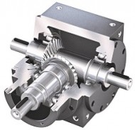
They are especially well suited to any case in which the drive path requires turning a corner or where several devices are supplied by one motor, which is a model always found in automation and factory construction lines.
Real Advantages of Bevel Gears
- Bevel gears are utilized in different applications, which range from the aerospace sector (high-velocity straight and spiral bevel gears, particular steels and functions, air pre-heater, etc.) to the mining applications (stacker and scoop actuators, wheeled excavators, dredges, conveyor belts, mill actuators, etc.).
- They are also usual in sand mixers and conical mills, cooling towers, forklifts, ship actuators and propellers, pharmaceutical packaging machines, high-speed offset printing, polyethylene sheet production, automotive devices, and rail transmissions.
- Angled bevel gears are employed for small spaces in robotics, whereas in ferrous metallurgy, they are utilized in vertical supports of the rolling mill.
- In the case of food processing, bevel gears play an important role in the processing and packaging of food and the instruments of can manufacturing.
Now that you understand all the advantages and features of bevel gear, you might want to go one step further and begin to apply them to your special projects.
Buy Equipment or Ask for a Service
By using Linquip RFQ Service, you can expect to receive quotations from various suppliers across multiple industries and regions.
Click Here to Request a Quotation From Suppliers and Service Providers
Read More on Linquip



Hi I’m looking for the parts on my Riccar mighty sewing machine the gear that supports the stich selector fall apart.
Thanks for visiting our website, Liza! You are invited to visit our Industrial Tools & Equipment page, where you can find your proper instrument. You can also ask your question from our thousands of experts available on the Linquip website.