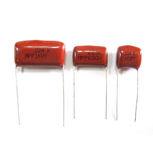
Film capacitors, film dielectric capacitors, plastic film capacitors, or polymer film capacitors are electrical capacitors with an insulating plastic film as the dielectric occasionally combined with paper as the carrier of the electrodes, and referred to as “film caps” or “power film capacitors.”
Paper capacitors were utilized in decoupling circuits prior to the introduction of film capacitors. The impregnated paper was layered with metal strips and twisted into cylindrical shapes to make paper capacitors. However, because these capacitors used paper as a dielectric, they were not only sensitive to natural problems but were also extremely large. As a result, scientists began looking for a remedy that would alleviate these issues.
There was a time when the plastic industry was expanding, and scientists discovered how using specific plastic films as dielectrics provided long-term electrical parameter stability. It also helped to reduce the size by replacing multiple layers of paper with only a few sheets of plastic. As technology progressed, the size of these capacitors shrank as thinner polymers with high dependability became available.
What is a Film Capacitor?
Capacitors are a type of essential passive electrical component that can be found in a variety of circuits. If you’re a DIY enthusiast who’s interested in electronic circuits, knowing the many types of capacitors is essential for properly using them in circuits. In this post, we’ll explain how to decode and use film capacitors, which are one of the most prevalent forms of capacitors. Please keep in mind that Film Capacitors go by a variety of names, including Polyester Capacitors and Mylar Capacitors. This page covers all of them in general.
Capacitors using a thin plastic film as the dielectric are known as film capacitors. A complex film drawing procedure is used to make this film very thin. Depending on the capacitor’s requirements, the film may be metalized or left untreated after manufacturing. The assembly is then fitted into a casing that protects it from environmental conditions after the electrodes have been installed.
Because of their reliability, low inductance, and low cost, they are employed in a variety of applications. Polyester film, metalized film, PTFE film, polypropylene film, and polystyrene film are all examples of film capacitors. The material used as the dielectric is the main distinction between various capacitor types, and the correct dielectric must be chosen based on the application.
Heat-resistant PTFE film capacitors are employed in aerospace and military technology, for example, while metalized polyester film capacitors are utilized in applications that demand long-term stability at a low cost. If cost is more important than performance, less expensive plastics are chosen.
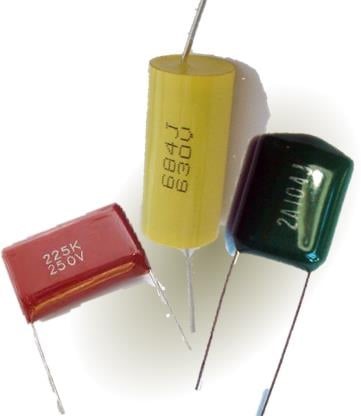
Characteristics and Construction of Film Capacitors
Because of their exceptional features, film capacitors are frequently utilized. This capacitor is non-polarized, making it acceptable for AC signal and power applications. Film capacitors may be produced with extremely precise capacitance values, and they keep that value for longer than other capacitor kinds. This means that, in comparison to other capacitor types, such as the electrolytic capacitor, the aging process is often slower. Film capacitors have a long shelf life and are extremely dependable, with a very low average failure rate. They have a low ESR (Equivalent Series Resistance), low self-inductance (ESL), and low dissipation factors as a result.
They can tolerate voltages up to kilovolts and deliver extremely strong surge current bursts. There is a specific class of film capacitors known as power film capacitors that can tolerate reactive power in excess of 200 volt-amperes. Special screw-type terminals that can handle high currents may be used on these capacitors. Because power film capacitors must occasionally be replaced in the field, screw-type terminals have replaced soldered connectors. Their better electrical characteristics and stability, unfortunately, come at a cost. Because film capacitors are bigger than electrolytic capacitors, only a few SMT (Surface – Mount Technology) packages are available. They can also catch fire if they are overloaded, but this is a frequent symptom of other capacitor types.
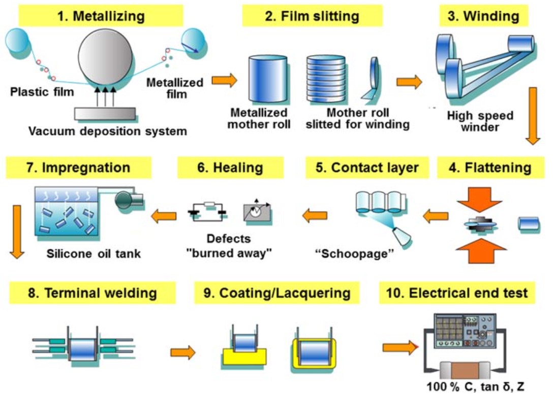
Film capacitors are formed of a thin dielectric film that is metalized on one side or not at all. The film is very thin, with a thickness of less than one micrometer. The film is sliced into ribbons after it has been drawn to the proper thickness. The ribbon width is determined by the capacity of the capacitor being manufactured. Two film ribbons are twisted together to form a roll, which is then pressed into an oval shape to fit into a rectangular case. Because rectangular components take up less space on the printed circuit board, this is crucial. Each of the two electrodes is connected to one of the films to create electrodes. Using the self-healing feature of film capacitors, a voltage is provided to burn out any defects. The interior of the box is then hermetically sealed with silicon oil to protect the film roll from moisture and dipped in plastic.
The flow diagram below depicts the numerous procedures involved in the production of a metalized film capacitor.
Capacitances of typical film capacitors range from less than 1nF to more than 30µF. They are available in voltage levels ranging from 50V to over 2kV. They may be made to work in high-vibration automotive situations, as well as high-temperature and high-power applications. Film capacitors provide minimal losses and great efficiency, as well as a long life span.
Various Types of Film Capacitors
The plastic industry began to manufacture thinner and more durable goods soon after the first film capacitor was introduced. Over the years, several types of plastic film capacitors have been employed as dielectrics to suit various circuit applications. Some film capacitors have plastic films that are simply placed between aluminum foils, while others have the plastic film metalized through a process in which metal is deposited on the film itself. Film capacitors are generally divided into two types based on their construction. It’s worth noting that the classification is solely based on structure.
Film/Foil Capacitors
The film/foil capacitor, as the name implies, utilizes plastic films as a dielectric and is housed between two layers of aluminum foil electrodes. The metallic layers do not come into contact with each other since these interleaved layers are so organized. Inductive or non-inductive capacitors are available.
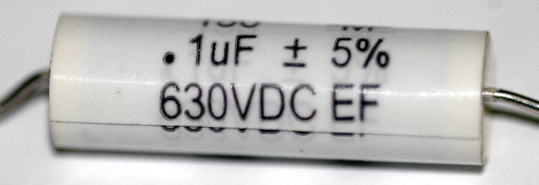
An inductive film foil capacitor is coiled so that the aluminum foils are in the middle of the two films. The aluminum foils are joined to one another by a leading wire that holds the entire coil together. In a noninductive fil foil capacitor, the aluminum foils are positioned so that each foil is partially exposed to the films.
Plastic film capacitors have the following characteristics:
- High insulation resistance
- Capacity stability is good.
- Even at high frequencies, efficiency is high.
- Polypropylene (PP)/Polyethylene terephthalate (PET)/Polytetrafluoroethylene (PTFE) were employed as dielectrics.
Metalized Film Capacitors
The fundamental difference between a film foil capacitor and a metalized capacitor is that the latter’s metallic electrodes are fused into either side of the plastic dielectric rather than being layered. It offers higher stability and smaller dimensions than a film foil capacitor although costing more and requiring an extra step in the manufacturing process. To get the necessary capacitance value, the plastic sheet thickness can be as low as 0.6µm.
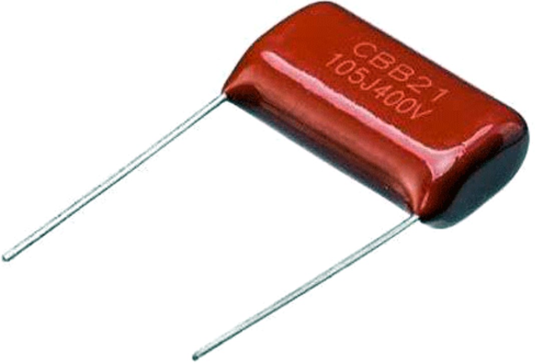
Metalized film capacitors have the following characteristics:
- Self-healing property: This property allows the capacitor to self-repair rather than short-circuit if the electrodes come into contact with each other. As a result, the capacitor’s reliability improves.
- Size and shape are both compact.
- Polypropylene (PP), Polyethylene terephthalate (PET), Polytetrafluoroethylene (PTFE), and Polyphenylene Sulfide (PPS) were employed as dielectrics.
Differences between Film Capacitors, Electrolytic Capacitors, and Ceramic Capacitor
The type of dielectric employed and their design are the first obvious differences between these three capacitors. While film capacitors utilize thin plastic sheets as dielectric, ceramic capacitors use sheets composed of ceramic material. They’re both bipolar in nature. Electrolytic capacitors, on the other hand, are polar in nature and use oxides as the dielectric.
Their manufacturing and dielectric properties have a significant impact on their performance. Plastic film/metalized film capacitors come in a wide range of capacitance values, as previously mentioned. Ceramic capacitors, on the other hand, are only suitable for circuits requiring low capacitance. Film capacitors are chosen over ceramic capacitors for specific applications such as analog signal processing and audio circuits due to their low distortion factor. Ceramic capacitors also have large nonlinearities at high capacitances, which has an impact on circuit performance.
Capacitors with high capacitance and a cheap cost are desirable for applications such as coupling/decoupling circuits. As a result, both electrolytic and film capacitors are viable solutions. The capacitor’s ESR (Equivalent Series Resistance) and ESL (Equivalent Series Inductance) values are also important to consider when designing such circuits. When compared to electrolytic capacitors, film capacitors have a lower ESR and ESL value, as well as a lower distortion factor, and are thus preferred over aluminum electrolytic capacitors.
Applications of Film Capacitors
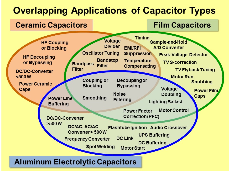
Low-power film capacitors are utilized as decoupling capacitors, filters, and A/D converters, whereas high-power variations are utilized in power electronics devices, X-ray flashes, phase shifters, and pulsed lasers. Safety capacitors, fluorescent light ballasts, electromagnetic interference suppression, and snubber capacitors are some of the other significant applications.
Fluorescent lights require lighting ballasts to start and operate properly. When a ballast fails, the light will flicker or not turn on at all. Older ballasts relied solely on an inductor, which has a low power factor. The new designs feature a switched power supply with power factor adjustment provided by film capacitors.
Protective devices known as snubber capacitors dampen or “snub” inductive kickback voltage spikes. Film capacitors are commonly used in these circuits due to their low self-inductance, high peak current, and low ESR, all of which are important in a snubber design. In this type of circuit, polypropylene film capacitors are most commonly employed. Snubbers are utilized in a variety of electrical devices, including flyback DC-DC converters and other power electronics devices.
Film capacitors can also be utilized as voltage smoothing capacitors, filters, and audio crossovers in more traditional applications. They can store energy and then release it in a high-current pulse when necessary. Pulsed lasers and lightning discharges are both powered by high-current electrical pulses.
The following figure demonstrates applications of various types of capacitors and their overlapping applications:
Advantages and Disadvantages
Advantages
- Film capacitors made of polypropylene can be used in Class 1 applications.
- High-quality factors, very low dissipation factors, and low inductance values (ESL)
- When contrasted to ceramic capacitors, there is no microphonics.
- Self-healing properties in the metalized construction
- High-rated voltages of up to kV are achievable
- When compared to electrolytic capacitors, the ripple current is much higher
- When compared to electrolytic capacitors of comparable value, there is far less aging
- Surge current pulses of high and very high magnitudes are achievable.
Disadvantages
- Capacitors with a larger physical size than electrolytic capacitors
- Surface-mount technology (SMT) packaging has a restricted number of kinds
- Film/foil types do not have the potential to self-heal (irreversible short circuit)
- Under overload conditions, it may become combustible.
FAQs
What Is the Use of Film Capacitor?
PP film capacitors are utilized in pulsed power energy discharge applications, induction heating, and as AC capacitors for electrical distribution. These capacitors have AC voltage ratings of up to 400 kV.
What Is the Difference Between Ceramic and Film Capacitors?
In comparison to film capacitors, ceramic capacitors’ frequency and voltage responses are somewhat non-linear. Another problem with ceramic capacitors is that they have a tendency to act like microphones, taking up ambient sound and altering the voltage across them accordingly.
What is the Active Part of an Electrolytic and Film Capacitor?
The active part of electrolytic capacitors, known as the wound cell, is constructed of aluminum (anode and cathode foil), paper, and electrolyte, whereas the film capacitor’s electrodes are made of metal-coated plastic film.
Can I Use Ceramic Instead of Film Capacitor?
Yes, they can be swapped out, however, ceramic disc capacitors have a far more nonlinear voltage and frequency response than film capacitors. Microphonic ceramic caps are also available.
Are Film Capacitors Good for Audio?
Plastic film capacitors from WIMA have the optimum qualities for all types of audio applications.
You can also visit this nice link for more information about film capacitors.
Buy Equipment or Ask for a Service
By using Linquip RFQ Service, you can expect to receive quotations from various suppliers across multiple industries and regions.
Click Here to Request a Quotation From Suppliers and Service Providers
Read More In Linquip
- Types of Electric Circuits: All Classification with Application
- How does a Circuit Breaker Work?
- What is Resistive Circuit
- What is Linear Circuit
- What is RL Circuit
- What is RC Circuit?
- What is RLC Circuit
- What is Capacitive Circuit?
- Types of Resistor: Classification, Application, and Finally Clarification
- What is Parallel Circuit? Definition & Example
- What is Series Circuit? Definition & Example
- What is Closed Circuit? Definition & Example
- What is Short Circuit? A Clear Definition & Protection Guide
- Difference Between Linear and Nonlinear Circuits
- What are the Differences Between Series and Parallel Circuits?
- The 8 Best Circuit Breaker Locators in 2022

