What Is Auto Transformer? An Auto Transformer is a laminated core transformer with only one winding wrapped on it. An autotransformer is similar to a two-winding transformer, but the primary and secondary windings are not connected in the same way. Both the major and secondary sides share a portion of the winding. When the load is on, a portion of the load current is taken directly from the supply, while the remainder is obtained by transformer action. A voltage regulator is an autotransformer.
What is Auto Transformer?
Explanation of Auto Transformer with Circuit Diagram
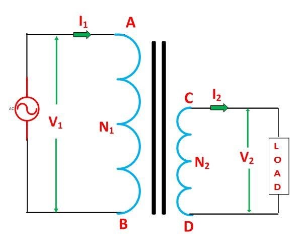
In a conventional transformer, the main and secondary windings are electrically isolated yet magnetically coupled, as illustrated in the diagram below. The main and secondary windings of an auto transformer are coupled magnetically as well as electrically. In reality, both main and secondary windings share a portion of the single continuous winding.

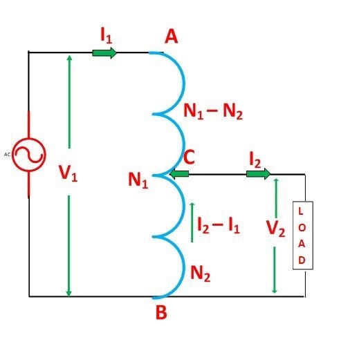
Based on the structure, there are two types of auto transformers. There is continuous winding in one sort of transformer, with taps pulled out at opportune locations specified by the required secondary voltage. Another sort of auto transformer, on the other hand, has two or more separate coils that are electrically coupled to make a continuous winding. The Autotransformer’s construction is depicted in the diagram below.

The main winding AB is used to tap at C, resulting in CB acting as a secondary winding. The load is linked across CB, while the supply voltage is applied across AB. The tapping might be either constant or varied. When an alternating flux is created in the core by applying an AC voltage V1 across AB, an EMF E1 is induced in the winding AB. The secondary circuit absorbs a portion of the induced EMF.
Let V1 as primary applied voltage, V2 as the secondary voltage on the load, I1 as primary current, I2 as load current, N1 as the number of turns between A and B, and N2 as the number of turns between C and B. If we neglect no-load current, leakage reactance, and wastes,
So V1 = E1 and V2 = E2.
As a result, the transformation ratio:
K= \frac{V_2}{V_1}=\frac{N_2}{N_1}=\frac{I_1}{I_2}
The current I2 is in phase opposition to I1 because secondary ampere-turns are opposite primary ampere-turns. The voltage in the secondary is lower than in the main. As a result, current I2 is greater than current I1. As a result, the current passing through section BC is (I2 – I1).
The ampere-turns (IT) according to section BC = turns x current.
{IT}_{BC}=(I_2-I_1)N_2=I_1N_1(1-K)
{IT}_{AC}=I_1(N_1-N_2)=I_1N_1(1-K)
The ampere-turns due to section BC and AC balance each other, as shown in the above equations, which is typical of transformer operation.
When compared to a traditional two-winding transformer, auto transformers save copper. The weight of copper is related to the cross-sectional length and area of the conductor. The conductor’s length is proportional to the number of turns, and the cross-section is proportional to the current multiplied by the number of turns.
Now, based on the autotransformer depicted in figure (2), the weight of copper required in an auto transformer is
Wa = weight of copper in part AC + weight of copper in part CB
As a result
{W}_{a}\propto I_1N_1+I_2N_2-2I_1N_2
If the same job is done using an ordinary two-winding transformer like the one depicted in figure (1), the total weight of copper required in the conventional transformer is
W0 = weight of copper on its primary section + weight of copper on its secondary section
As a result,
{W}_{0}\propto I_1N_1+I_2N_2
The weight of copper in an autotransformer compared to the weight of copper in a regular transformer is now presented as
{W}_{a}=(1-k)W_0
Copper savings from utilizing an auto transformer are calculated as follows: weight of copper required in a conventional transformer – weight of copper required in an auto transformer.
As a result, saving of copper = K x weight of copper required for two windings of the transformer.
As a result, as the transformation ratio approaches unity, copper savings grow. When the value of K is approximately equal to unity, the auto transformer is utilized. Visit here to explore more about the working principle of an auto transformer.
Read More on Linquip
- working principle of transformer: discover the mechanism involved in the operation
- What is Power Transformer?
- What is Step-Down Transformer and Its Application?
- What Is Electrical Transformer
Advantages of Auto Transformer
The following are some of the advantages of using an auto transformer:
- For a transformation ratio of 2, the auto transformer would be around half the size of a two-winding transformer. The size would be 95 percent for a transformation ratio of 20, for example. Of course, the material cost savings are not in the same proportion. When the transformer ratio is low, such as less than 2, cost savings are noticeable. As a result, the auto transformer is smaller and less expensive.
- The efficiency of an auto transformer is better than that of two winding transformers. Because of the reduced transformer material, there is less ohmic loss and core loss.
- The voltage control of an auto transformer is better because the voltage drop in resistance and reactance of the single winding is lower.
- Less expensive
- Improved regulation
- When compared to a standard two-winding transformer of the same rating, there are fewer losses.
Disadvantages of Auto transformer
- The secondary winding is not isolated from the main winding, which is one of the key disadvantages of the auto transformer and one of the reasons why it is not extensively employed.
- If a break in the secondary winding of an auto transformer used to deliver low voltage from a high voltage occurs, the whole primary voltage is applied to the secondary terminal, posing a threat to the user and the equipment. As a result, the auto transformer should not be utilized to link high and low-voltage systems.
- Only used in a few instances where a little difference in output voltage from input voltage is necessary.
- The lower voltage circuit is susceptible to being impressed by greater voltage due to the electrical conductivity of the main and secondary windings. To avoid a lower voltage circuit failure, the low voltage circuit must be designed to handle the greater voltage.
- The impedance is low because the leakage flux between the primary and secondary windings is modest. Under fault situations, this leads to more severe short circuit currents.
- Except when employing interlinked starred connections, the connections on the primary and secondary sides must be identical. This causes issues since the primary and secondary phase angles change, especially in the case of a delta/delta connection.
- It is not feasible to ground the neutral of one side solely in a star/star-linked auto transformer due to the shared neutral. Their neutrality should be either earth or isolated on both sides.
- When voltage adjustment tappings are present, maintaining the electromagnetic balance of the winding becomes more challenging. It should be noted that the addition of tapping to an auto transformer significantly increases the transformer’s frame size. If the tapping range is particularly large, the early cost savings are negated by a major incident.
Applications of Auto transformer

- It’s utilized as a starter to provide up to 50% to 60% of full voltage to a squirrel cage induction motor’s stator during startup.
- It’s used to fix a voltage drop in a distribution cable by giving it a little boost.
- It serves as a voltage regulator as well.
- Power transmission and distribution systems, as well as audio systems and trains, all use this material.
- Voltage fluctuations are compensated for in distribution systems by the increasing supply voltage.
- Induction and synchronous motors are started with auto transformers with several taps.
- In a laboratory or when a continuous variable across a wide range is required, an auto transformer is applied as a variac.
Buy Equipment or Ask for a Service
By using Linquip RFQ Service, you can expect to receive quotations from various suppliers across multiple industries and regions.
Click Here to Request a Quotation From Suppliers and Service Providers


Intrested in auto transfer of rating 3kva for domestic purposes.
Thanks for visiting our website, Rakesh! You can find your instrument in our Industrial Equipment page, where you can find multiple choices according to your application and demand.
Hello
Your article and information about electrical components are very helpful and educational, Thank you.
I am wondering if you could help me out with my problem ?
I’m running a 3 Ph. Ac generator it has an output of 365 Volt and 35 Amps
the load is a 10 Hp. 3 Ph. induction motor it needs 230 to 240 Volts to run correctly
With the higher Voltage it will overheat.
Can you please sell me a step down transformer that would reduce the Voltage from
365 to 230 or 240 Volts. Thanks
John
Thank you, John, for visiting our website. You are encouraged to visit our experts’ page, where you can find numerous experts in the field of electrical engineering that can help you with your problem.