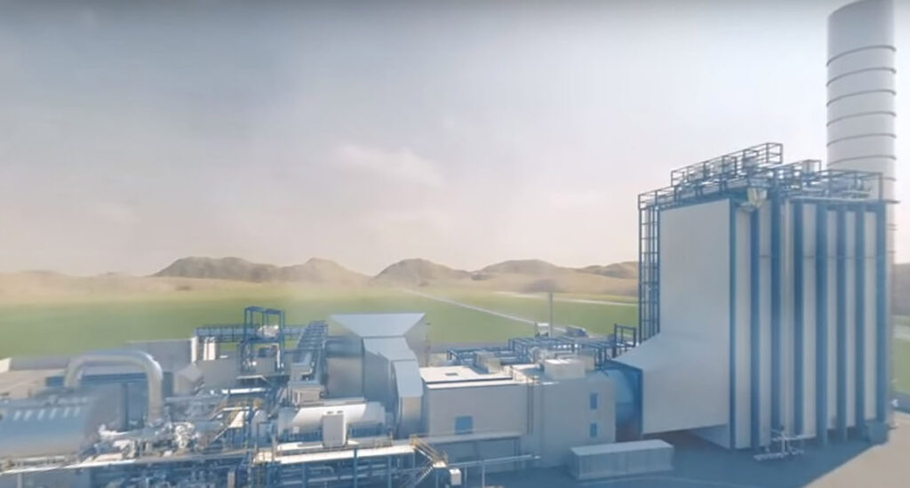
What is Combined Cycle Power Plant – A combined cycle power plant is a collection of heat engines that collaborate to transform heat energy from one source of heat into mechanical energy. A combined cycle gas turbine (CCGT) plant is the most popular design for producing power on land. The same idea is employed in combined gas and steam (COGAS) plants, which are utilized in maritime propulsion. The overall efficiency is increased by combining two or more thermodynamic cycles, which lowers fuel cost.
On Linquip website, among the many options available to you, you will find all the information you need to know about Power Plants, as well as information regarding this marketplace. You can count on Linquip to provide you with as much general and reliable information about this topic, whether you’re a professional or a customer looking for a proper company. We recommend you review a list of all Industry Directories available in Linquip.
We would be delighted to provide you with more information on how we can help you generate revenue within your industry. Don’t hesitate to contact us if you have any questions! With Linquip’s Solutions for Each Company Level, you will be able to upgrade the capabilities of your organization in order to gain a competitive edge by taking advantage of a wide range of options to enhance your organization’s performance. If you are looking for the simplest or the most sophisticated marketing and advertising package for your business, we can help you ensure that your company gets as many customers as possible to grow your business.
What is a Combined Cycle Power Plant?
A combined cycle power plant is a collection of heat engines that collaborate to transform heat energy from one source of heat into mechanical energy. A combined cycle gas turbine (CCGT) plant is the most popular design for producing power on land. The same idea is employed in combined gas and steam (COGAS) plants, which are utilized in maritime propulsion. The overall efficiency is increased by combining two or more thermodynamic cycles, which lowers fuel cost.
The basic idea is that when the first engine has finished its cycle, the working fluid (the exhaust) is still hot enough for a second, succeeding heat engine to use to generate energy. In order for the two engines to use separate operating fluids, the heat is often transferred through a heat exchanger.
The overall efficiency may be raised by 50–60% by producing electricity from several different workstreams. To put it another way, from a system’s total efficiency of, let’s say, 34% for a simple cycle to as high as 64% net for the turbine alone in certain circumstances for a combined cycle. This is more than a Carnot cycle’s theoretical efficiency by more than 84%. The residual heat (i.e., hot exhaust gas) from combustion in a non-combined cycle heat engine is lost since heat engines can only employ a portion of the energy from their fuel.
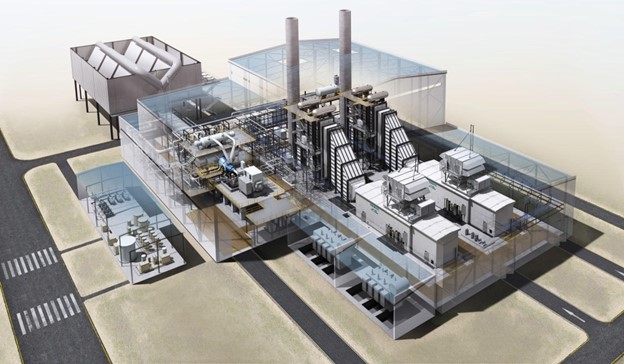
Basics of a Combined Cycle
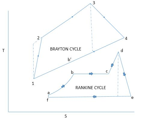
Two power plant cycles make up the basic combined cycle’s thermodynamic cycle. One is a steam turbine cycle called the Rankine cycle, and the other is a gas turbine cycle called the Joule or Brayton cycle. The gas turbine power plant cycle, which is 1-2-3-4-1, is the topping cycle. It shows how heat and work are transferred in an area with high temperatures.
At a lower temperature, the Rankine steam cycle, represented by the letters a–b–c–d–e–f–a, is what is known as the bottoming cycle. In a waste heat recovery boiler, the bottoming cycle is when heat energy from the high-temperature exhaust gas is transferred to water and steam. Gas turbine exhaust rejects heat during the constant pressure process 4-1. In the processes a–b, b–c, and c–d, some of this heat is absorbed by the feed water, wet steam, and superheated steam.
Steam Generators
The high-temperature exhaust gasses from a gas turbine power plant are the source of the steam power plant’s heat input. A steam turbine can be powered by the steam thusly produced. Economiser, evaporator, and superheater make up the three components of a waste heat recovery boiler (WHRB).
Cheng Cycle
A more straightforward version of a combined cycle is the Cheng cycle, which replaces the steam turbine with a direct steam injection into the combustion turbine. This method, which has been in use since the middle of the 1970s, enables waste heat recovery with less overall complexity but at the expense of the extra power and redundancy of a genuine combined cycle system. It cannot employ an extra steam turbine or generator as a backup or supplemental power source since it lacks one. It bears the name of D. Y. Cheng, an American professor who patented the concept in 1976.
Design Principles of a Combined Cycle Power Plant
The temperature differential between the heat entering the engine and the exhaust heat exiting the engine limits the efficiency of a heat engine or the portion of input heat energy that can be transformed into meaningful work.
Water is the working medium in thermal power plants. Strong, substantial components are needed for high-pressure steam. Instead of cheap steel, costly alloys composed of nickel or cobalt are needed at high temperatures. The lower temperature of a steam plant is determined by the temperature of the cooling water, whereas these alloys restrict practical steam temperatures to 655 °C. With these restrictions, a steam plant has a fixed top efficiency of 35-42%.
The compressor, combustor, and turbine are all components of an open circuit gas turbine cycle. Gas turbines may employ less expensive materials since there is less metal that needs to endure the high temperatures and pressures. The input temperature (also known as the firing temperature) to the turbine during this cycle ranges from 900 to 1,400 °C. The flue gas’s output temperature ranges from 450 to 650 °C. Since steam is the working fluid, this value is high enough to produce heat for a second cycle (a Rankine cycle).
A heat recovery steam generator (HRSG) with live steam between 420 and 580 °C is used in a combined cycle power plant to create steam from the heat of the gas turbine exhaust. The water from lakes, rivers, the sea, or cooling towers is typically used to cool the condenser in the Rankine cycle. It may only be 15 °C at this time.
Typical Size
The cost of the plant is heavily influenced by plant size. The economies of scale (lower starting cost per kilowatt) and increased efficiency favor the bigger plant sizes.
A typical set for large-scale power generation would have a main gas turbine with an output of 270 MW, a secondary steam turbine with an output of 130 MW, and a combined output of 400 MW. One to six of these sets may make up a conventional power plant.
At least four companies produce gas turbines for large-scale power generation: General Electric, Siemens, Mitsubishi-Hitachi, and Ansaldo Energia. Additionally, these organizations are creating, evaluating, and/or selling gas turbines with capacities greater than 300 MW (for 60 Hz applications) and 400 MW (for 50 Hz applications). A combined cycle block or unit comprises one or more of these gas turbines, each equipped with a waste heat steam generator set up to deliver steam to one or more steam turbines. Three main manufacturers (Alstom, General Electric, and Siemens) produce combined cycle block sizes ranging from 50 MW to well over 1300 MW at prices of about $670/kW.
Unfired Boiler
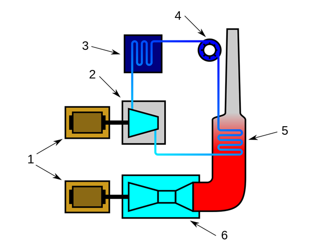
Item 5 in the COGAS graphic above represents the heat recovery boiler. As hot gas turbine exhaust exits the boiler, it first travels through the superheater, then the evaporator, and lastly, the economizer section. After reaching saturation temperature in the water or steam circuit, feed water enters through the economizer and subsequently leaves. Finally, it passes via the superheater and evaporator. The gasses leaving the heat recovery boiler will have a greater temperature if the gasses entering it are at a higher temperature.
Dual Pressure Boiler
A dual pressure boiler is frequently used to extract the most heat possible from the gasses leaving the high-temperature cycle. Two water/steam drums are present. The low-pressure economizer or evaporator is linked to the low-pressure drum. The low-temperature region of the turbine exhaust gasses is where the low-pressure steam is produced. The low-temperature turbine receives the low-pressure steam. The low-pressure circuit can be equipped with a superheater.
A booster pump moves a portion of the supply water from the low-pressure zone to the high-pressure economizer. The water is heated to saturation temperature by this economizer. The high-pressure turbine receives this saturated water after it has passed through the boiler’s high-temperature zone.
Supplementary Firing
After the gas turbine, the HRSG can be made to burn additional fuel. Duct burners are another name for supplementary burners. Because some oxygen is still present in the turbine exhaust gas (flue gas), duct burning is conceivable. Due to temperature restrictions at the gas turbine’s input, the turbine must consume more air than is stoichiometrically necessary to burn the fuel. A portion of the compressed air flow in gas turbine designs frequently bypasses the burner to cool the turbine blades. A regenerative air preheater is unnecessary, as it would be in a typical steam plant because the turbine exhaust is already hot. However, a duct-burning steam plant may still run even when the gas turbine cannot due to a fresh air fan blowing straight into the duct.
The thermal efficiency of a combined cycle power plant is better without supplemental firing. However, by enabling a ship to function even with system failures, more adaptable plant operations make maritime CCGTs safer. A mobile plant with flexibility can generate greater revenue. The burning duct increases the temperature of the flue, which boosts the amount or temperature of the steam (e.g., to 84 bar, 525 degree Celsius). The steam cycle is more effective as a result. Because duct burners may operate at extremely high efficiency with partial loads, supplemental fire enables the plant to adapt to changes in electrical load. In order to make up for the failure of another unit, it may be possible to increase steam production. Additionally, coal can be used as a cost-effective supplemental fuel in the steam generator.
Exhaust temperatures can increase from 600 °C (GT exhaust) to 800 °C or even 1000 °C with supplemental firing. Most combined cycles do not get more efficient with further firing. If burnt to 700–750 °C, it can increase the efficiency of a single boiler; but, for a plant with numerous boilers, the plant’s flexibility should be the main selling point.
When the maximum amount of fuel is burned with the oxygen present in the gas turbine exhaust, this situation is referred to as “maximum supplemental firing.”
Efficiency of a Combined Cycle Power Plant
High input temperatures and low output temperatures can be attained by combining the gas and steam cycles. The cycles’ combined efficiency benefits from sharing the same fuel source. Therefore, a combined cycle plant has a thermodynamic cycle that runs between the high firing temperature of the gas turbine and the waste heat temperature from the steam cycle’s condensers. This wide range indicates that the cycle’s Carnot efficiency is excellent. Even though it is less than the Carnot efficiency, the real efficiency is still more than any plant’s standalone efficiency.
When operating new, that is, unaged, and at the continuous output, which is ideal conditions, the electric efficiency of a combined cycle power plant may be above 60%. This is because electric energy is produced as a percentage of the lower heating value of the fuel used. The delivery of low-temperature heat energy for industrial operations, district heating, and other applications is possible with combined cycle thermal units, just like with single cycle thermal units. These power facilities are referred to as combined heat and power (CHP) plants, and this process is known as cogeneration.
On a lower heating value and gross output basis, total cycle efficiencies in service are often greater than 50%. The majority of combined cycle units, particularly the bigger ones, have a peak, steady-state LHV efficiency of 55 to 59%.
Natural Gas Integrated Power And Syngas (Hydrogen) Generation Cycle
A natural gas integrated power and syngas (hydrogen) generating cycle makes use of semi-closed (also known as closed) gas turbine cycles, in which fuel is burned with only pure oxygen while the cycle’s working fluid, a mixture of the combustion products CO2 and H2O, is present (steam).
According to the integrated cycle, methane (the primary component of natural gas) is combined with working fluid prior to combustion and converted into syngas (a mixture of H2 and CO) in a catalytic adiabatic reactor using the sensible heat of the hot working fluid that is, in the simplest scenario, leaving the gas turbine outlet. The majority of created syngas (about 75%) is fed into the gas-turbine cycle’s combustion chamber to produce electricity, while a smaller portion (around 25%) is removed from the power-generating cycle to be converted to chemicals, fertilizers, synthetic fuels, etc. The exergy study provides evidence for the thermodynamic advantage brought about by this adjustment. Several technical ways exist to remove syngas from the cycle and separate it from the working fluid.
Due to the lack of NOx and the emission of non-diluted (in N2) and CO2 in the flue gas, all the environmental benefits of semi-closed gas turbine cycles remain the same. The following clarification reveals a consequence of integration. At a maximum temperature in the cycle of about 1300 °C, the net-power generation efficiency can reach levels higher than 60% by assigning the efficiency of syngas production in the incorporated cycle a value equal to a regular syngas production efficiency through steam-methane reforming.
At the Chemistry Department of Moscow State Lomonosov University (Russia), M. Safonov, M. Granovskii, and S. Pozharskii first presented the natural gas integrated cycle with an adiabatic catalytic reactor in 1993.
Download What is Combined Cycle Power Plant PDF
You can download the PDF format of this post from here.
Buy Equipment or Ask for a Service
By using Linquip RFQ Service, you can expect to receive quotations from various suppliers across multiple industries and regions.
Click Here to Request a Quotation From Suppliers and Service Providers
Read More In Linquip
- Nuclear Power Plant Diagram: A Complete Guide
- Thermal Power Plant Diagram: All You Need to Know About It
- What is a Power Plant? (Clear Guide)
- How Does a Power Plant Work? (Ultimate Guide) + PDF
- 9 Different Types of Power Plants + PDf
- What is CHP? (Combined Heat and Power) + Types & Working Principle
- More Informtion about Power Plant System
- More Details about Power Plant Generator
- More Details about Thermal Power Plant Generators
- Read More Information about Steam Power Plant Generators
- More Information about Nuclear Power Plant Generators
- Read More Information about Hydro Power Plant Generators
- See List of Siemens Generators Products

