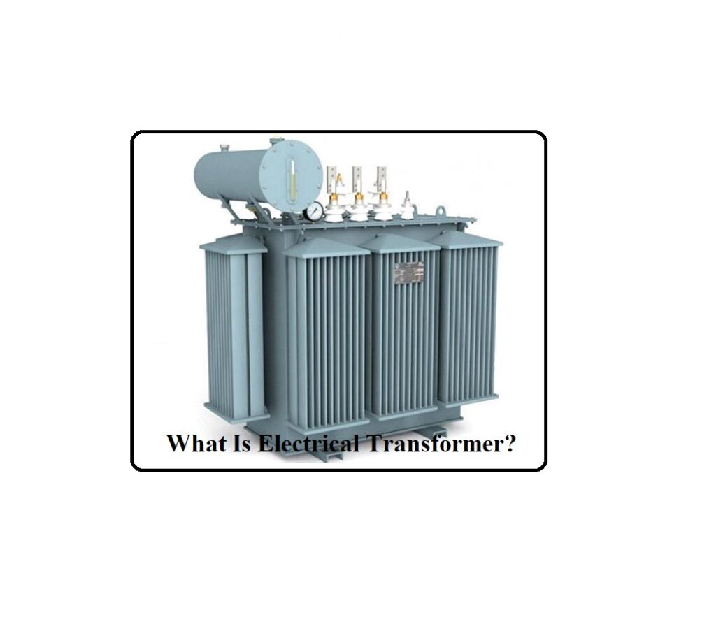
What Is Electrical Transformer? An Electrical Transformer is a type of passive electrical device that uses electromagnetic induction to transmit electrical energy from one circuit to another. It’s most typically used to ‘step up’ or ‘step down’ voltage levels between circuits.
What Is Electrical Transformer?
The massive power wires that crisscross our countryside or slither unnoticed beneath city streets transmit electricity from power stations to our homes at extremely high voltages. A power line’s voltage rating can range from 300,000 to 750,000 volts, and some lines operate at much greater voltages. However, the voltages used in our homes are hundreds of times lower, ranging from 110 to 250 volts.
If you tried to power a toaster or a television set with energy from a pylon, it would explode! (Don’t even consider it; the voltage in overhead cables will almost surely kill you.) As a result, there must be a mechanism to convert high-voltage electricity generated by power plants to lower-voltage electricity utilized in companies, offices, and residences. An electrical transformer is a piece of equipment that achieves this while humming with electromagnetic energy. Let’s look at how it works in more detail!
Working Principle of an Electrical Transformer
A transformer’s operation is relatively straightforward. Electrical energy can be exchanged between circuits using mutual induction between two or more windings (also known as coils). This concept is explored in greater depth later.
Transformer Theory
Assume you have a single alternating current-powered winding (also known as a coil). The flux created by the alternating current passing through the winding is continually changing and alternating.
Some of the alternating flux will be transferred to the second winding if it is brought close to this one. Because the amplitude and direction of this flux are always changing, there must be a changing flux linkage in the second winding or coil.
According to Faraday’s law of electromagnetic induction, an EMF will be induced in the second winding. Current will flow via the secondary winding if the circuit is closed. The following is the core understanding of how a transformer works.
To better illustrate this, let’s utilize electrical symbols. The ‘primary winding’ is the section that receives electrical energy from the source. This is the ‘First Coil’ in the diagram below.
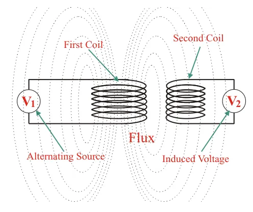
The ‘secondary winding’ is the winding that produces the desired output voltage due to mutual induction. In the figure, this is the ‘Second Coil.’
A step-up transformer is a device that improves the voltage between the primary and secondary sections. A step-down transformer, on the other hand, is a device that decreases the voltage between the main and secondary windings.
The number of turns on the primary and secondary sides of the transformer determines whether the transformer increases or decreases the voltage level.
If the primary coil has more turns than the secondary coil, the voltage will drop (step down). If the primary coil has less turns than the secondary coil, the voltage will rise (step up).
While the above transformer design is theoretically possible in an ideal transformer, in fact it is not particularly practical. This is because only a very small amount of the flux created by the first coil will join with the second coil in the open air. As a result, the current flowing through the closed circuit of the secondary winding will be extremely low (and difficult to measure).
The amount of connected flux with the second winding determines the rate of change in flux linkage. As a result, practically all of the flux from the primary section must completely be transferred to the secondary part. This is accomplished successfully and efficiently using a core type transformer. This produces a low-reluctance path that both windings can use.
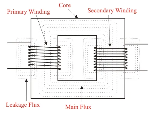
The transformer core’s function is to provide a low-reluctance path via which the primary winding’s greatest amount of flux is transmitted through and linked to the secondary winding. The inrush current of a transformer is the current that runs through it when it is turned on for the first time.
If you’d like an animated explanation, here’s a link to a video that explains how a transformer works.
Parts and Construction of an Electrical Transformer
A transformer’s three primary components are:
- Transformer primary winding
- Transformer Magnetic Core
- Transformer secondary winding
Primary Winding of Transformer
When coupled to an electrical source, it produces magnetic flux.
Magnetic Core of Transformer
The magnetic flux generated by the primary winding will flow down this low-reluctance channel, which will be coupled to the secondary winding, forming a closed magnetic circuit.
Secondary Winding of Transformer
The flux generated by the primary winding will pass through the core and connect to the secondary winding. This winding is also wound on the same core and provides the transformer’s required output.
Read More on Linquip
- working principle of transformer: discover the mechanism involved in the operation
- What is Power Transformer?
- What is Step-Down Transformer and Its Application?
- What Is Auto Transformer
Electrical Transformers in Your Home
As we’ve seen, towns and cities have a plethora of massive transformers that convert high-voltage electricity from incoming power lines into lower-voltages. However, there are several transformers in your home as well. Large electric appliances, such as washing machines and dishwashers, operate at relatively high voltages of 110–240 volts, whereas electronic devices, such as laptop computers and chargers for MP3 players and cellphones, operate at relatively low voltages: a laptop requires about 15 volts, an iPod charger requires 12 volts, and a cellphone requires less than 6 volts when its battery is charged.
Small transformers are integrated into electronic gadgets like these (typically installed at the end of the power cord) to convert the 110–240 volt home supply into a lower voltage that they can use. If you’ve ever wondered why enormous, hefty power lines for products like telephones exist, it’s because they contain transformers!
Induction Chargers
Many household transformers (such as those used to charge iPods and iPhones) are built to recharge rechargeable batteries. You can see how they work: energy goes into the transformer from your wall outlet, is converted to a lower voltage, and then flows into the batteries in your iPod or phone. But what happens if you have an electric toothbrush that doesn’t have a power cord? It is charged by a somewhat different sort of transformer, one of whose coils are located in the brush’s base and the other in the charger on which the brush rests. In our post on induction chargers, we explain how transformers like this function.
Transformers in Practice
If you have any of these transformer chargers at home (either regular or induction), you’ve probably noticed that they grow warm after a while. Because all transformers produce some waste heat, none of them are completely efficient: the secondary coil produces less electrical energy than we feed into the primary, with waste heat accounting for the majority of the difference.
Heat loss from a modest home cellphone charger is negligible (less than that from an old-fashioned incandescent light bulb) and is normally not a concern. However, the larger the transformer, the greater the current it can carry and the more heat it can generate.
The waste heat from a substation transformer which is about the width of a small car can be very significant: it can damage the transformer’s insulation, significantly reduce its life, and make it much less reliable (remember that hundreds or even thousands of people rely on the power from a single transformer, which must operate reliably not just from day to day, but from year to year).
As a result, a transformer’s expected temperature rise during operation is a critical consideration in its design. To determine how efficiently an outdoor transformer will perform, the average “load” (how heavily it is used), the seasonal range of outdoor (ambient) temperatures, and even altitude (which lowers the density of the air and hence how successfully it cools anything) must all be considered.
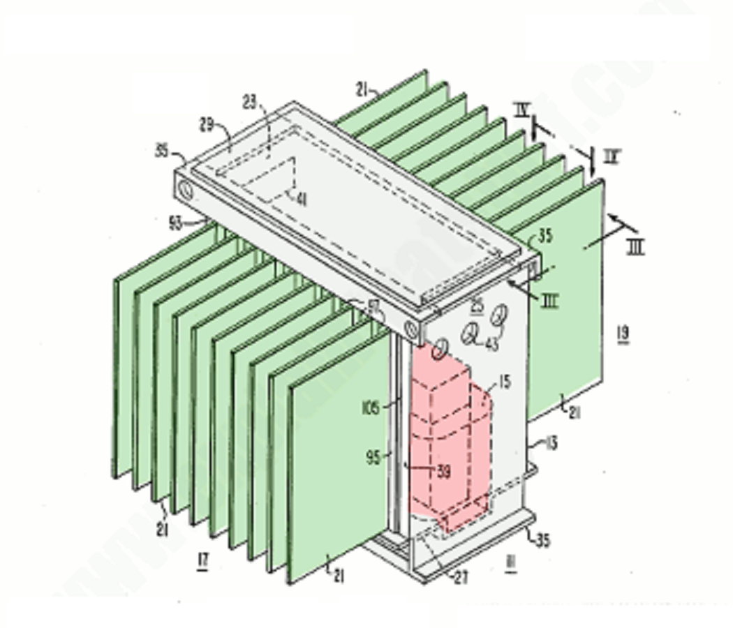
In practice, most large transformers have built-in cooling systems that remove waste heat using air, liquid (oil or water), or both. The major section of the transformer (the core, primary and secondary windings, and heat exchanger, pump, and cooling fins) is usually immersed in an oil tank.
The hot oil is pushed from the transformer’s top through the heat exchanger (which cools it down) and back into the bottom, ready to resume the cycle. Without the use of a separate pump, oil can sometimes travel throughout a cooling circuit by convection alone. To dissipate heat more effectively, some transformers incorporate electric fans that blow air past the heat exchanger’s cooling fins.
What Are Solid-State Electrical Transformers?
You’ve probably concluded from reading the preceding that transformers can be large, bulky, and inefficient at times. Since the mid-twentieth century, all kinds of interesting electric tricks that were formerly performed by huge (and occasionally mechanical) components have been performed electronically instead, employing “solid-state” technology. Switching and amplifying relays, for example, have been replaced by transistors, while magnetic hard drives have been gradually supplanted by flash memory (in such things as solid-state drives, SSDs, and USB memory sticks).
Electronic experts have been working on what is known as a solid-state transformer for several decades (SST). These are basically tiny, high-power, high-frequency semiconductor circuits that increase or decrease voltages more reliably and efficiently than traditional transformers; they’re also considerably more adjustable, making them more sensitive to supply and demand fluctuations.
As a result, “smart grids” (future power-transmission systems supplied by intermittent renewable energy sources like wind turbines and solar farms) will be a prominent application. Despite widespread interest, SST technology has yet to be widely used, but it is expected to become the most fascinating area of transformer design in the future.
Conclusion
Have you been converting voltage with a transformer? It is in your best interest to use a set-up or step-down voltage that is appropriate for your needs and requirements. These transformers are sometimes used to isolate the various portions of a circuit from one another. An isolation transformer would be required in this situation.
Buy Equipment or Ask for a Service
By using Linquip RFQ Service, you can expect to receive quotations from various suppliers across multiple industries and regions.
Click Here to Request a Quotation From Suppliers and Service Providers

