With about 60% of the global hydropower capacity in the world, Francis turbines are the most widely used type of hydro turbine. A Francis turbine is a large rotary machine that works to convert kinetic and potential energy into hydroelectricity. These modern equivalents of the water wheel have been used for over 135 years for industrial power generation, and more recently hydropower energy generation. In this article, we’ll discuss what a Francis turbine is, and how it works. Follow this new blog on Linquip to find out more.
Water strikes the runner blades radially and exits axially along its axis through a draft tube in a Francis turbine with a radial flow runner. The Francis turbine is a mixed flow turbine that provides a high curved rotating flow at the exit by passing the water via curved guide vanes. There are various Francis Turbines for Sale on Linquip from a range of Suppliers and Companies, as well as manufacturers and distributors.
Linquip’s website offers a comprehensive list of Francis turbine services to match your specific requirements. Vendors from Linquip can help you with this. To discover more about how to connect with a broad collection of service providers who consistently produce top-notch goods, please contact Francis Turbine Experts on Linquip.
⇒ View a List of Francis Turbine for Sale and Their Suppliers ⇐
What is a Francis Turbine?
Francis turbine definition is a combination of both impulse and reaction turbine, where the blades rotate using both reaction and impulse force of water flowing through them producing electricity more efficiently. Francis turbine is used for the production of electricity most frequently in medium or large-scale hydropower stations.
These turbines can be used for heads as low as 2 meters and as high as 300 meters. Additionally, these turbines are beneficial as they work equally well when positioned horizontally as they do when they are oriented vertically. The water going through a Francis turbine loses pressure, but stays at more or less the same speed, so it would be considered a reaction turbine.
Water enters these turbines radially meaning that it enters the turbine perpendicular to the rotational axis. Once entering the turbine, the water always flows inwards, towards the center. Once the water has flown through the turbine, it exits axially, parallel to the rotational axis. Francis turbines were the first hydraulic turbines that had a radial inflow, designed by American scientist James Francis.
Major Components of Francis Turbines With Diagram
- Spiral Casing
- Stay Vanes
- Guide Vanes
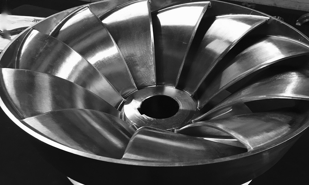
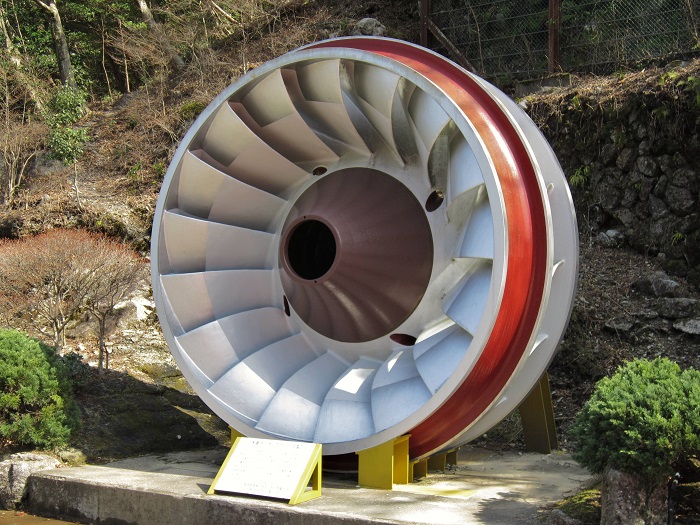
- Runner Blades
- Draft Tube
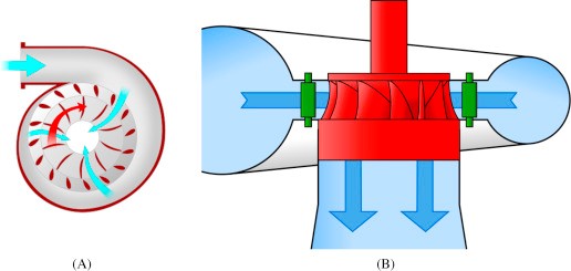
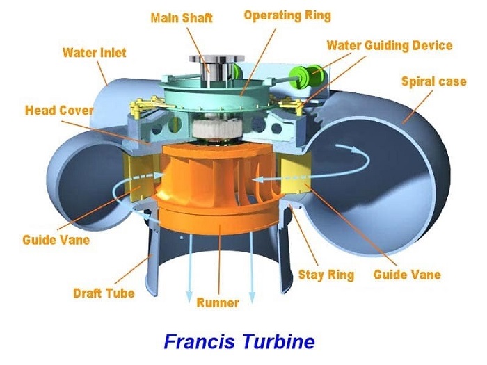
The diagram of various parts of a Francis turbine is shown in the figure below.
The description of each Francis turbine’s main component diagram is as follows.
-
Spiral Casing
The spiral casing is the inlet medium of water to the turbine. The water flowing from the reservoir or dam is made to pass through this pipe with high pressure. The blades of the turbines are circularly placed, which means the water striking the turbine’s blades should flow in the circular axis for efficient striking. So the spiral casing is used, but due to the circular movement of the water, it loses its pressure.
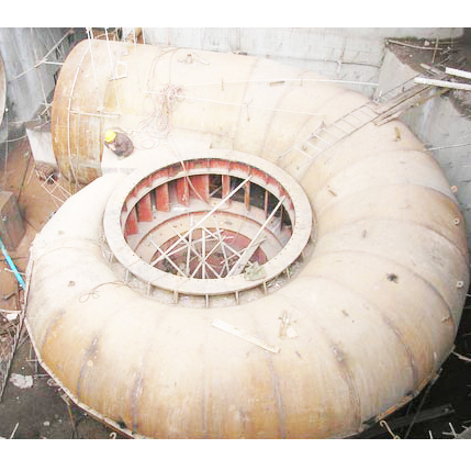
To maintain the same pressure the diameter of the casing is gradually reduced, thus, uniform momentum or velocity striking the runner blades.
-
Stay Vanes
Stay and guide vanes guide the water to the runner blades. Stay vanes remain stationary at their position and reduces the swirling of water due to radial flow, as it enters the runner blades, thus, making the turbine more efficient.
-
Guide Vanes
Guide vanes are not stationary, they change their angle as per the requirement to control the angle of striking of water to turbine blades to increase the efficiency. They also regulate the flow rate of water into the runner blades thus controlling the power output of a turbine according to the load on the turbine.
-
Runner Blades
Runner blades are the heart of any Francis turbine. These are the centers where the fluid strikes and the tangential force of the impact causes the shaft of the turbine to rotate, producing torque. Close attention to the design of blade angles at inlet and outlet is necessary, as these are major parameters affecting power production.
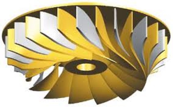
The runner blades have two parts. The lower half is made in the shape of a small bucket to rotate the turbine by using the impulse action of water. While the upper part of the blades uses the reaction force of water flowing through it. The runner rotates through these two forces.
-
Draft Tube
The pressure at the exit of the runner of the reaction turbine is generally less than atmospheric pressure. The water at the exit, cannot be directly discharged to the tailrace. A tube or pipe of the gradually increasing area is used for discharging water from the exit of the turbine to the tailrace.
This tube of the increasing area is called Draft Tube. One end of the tube is connected to the outlet of the runner. However, the other end is submerged below the level of water in the tail-race.
Francis Turbine Working Principle With Diagram
Francis turbines are employed regularly in hydroelectric power plants. In these power plants, high-pressure water enters the turbine through the snail-shell casing (the volute). This movement decreases the water pressure as it curls through the tube; however, the water’s speed remains unchanged. Following the passing through the volute, the water flows through the guide vanes and is directed towards the runner’s blades at optimum angles. Since the water crosses the precisely curved blades of the runner, the water is diverted somewhat sideways. This makes the water lose some part of its “whirl” motion. The water is also deflected in the axial direction to exit a draft tube to the tail race.
The mentioned tube reduces the water’s output velocity to gain the maximum amount of energy from the input water. The process of water being diverted through the runner blades results in a force that propels the blades to the opposite side as the water is deflected. That reaction force (as we know from Newton’s third law) is what makes power to be carried from the water to the turbine’s shaft, continuing rotation. Since the turbine moves due to that reaction force, Francis turbines are identified as reaction turbines. The process of altering the direction of the water flow also decreases the pressure within the turbine itself.
Francis turbines are the most favored hydraulic turbines. These turbines are the most stable workhorse of hydroelectric power stations. Francis turbine supplies about 60 percent of the global hydropower capacity, mainly because it can work efficiently under a wide range of working conditions. You can find the working principle of the Francis turbine here.
Cavitation:
Cavitation is a vital problem in hydraulic machines that negatively influences their performance and may cause damages. Cavitation is a phenomenon that manifests itself in the pitting of the metallic surfaces of turbine parts because of the formation of cavities. The reaction turbines operate under the low and medium head at a high specific speed and operate under variable pressure are prone to cavitation.
Cavitation in hydraulic machines negatively affects their performance and may cause severe damages. These damages can be summarized below:
- Erosion of material in turbine parts.
- Distortion of blade angle.
- Efficiency losses due to distortion or erosion.
Francis Turbine Efficiency
The performance and efficiency of the turbine are dependent on the design of the runner blades. In a Francis turbine, runner blades are divided into 2 parts. The lower half is made in the shape of a small bucket so that it uses the impulse action of water to rotate the turbine. The upper part of the blades uses the reaction force of water flowing through it. These two forces together make the runner rotate.
For these turbines to operate efficiently, water must reach all blades equally and flow is controlled by a casing which curls around the turbine in a spiral shape. This casing is called the volute (or spiral) casing. The casing feed water through a set of valves and fixed blades into the moving blades of the turbine rotor. When well designed, a Francis turbine can capture 90%–95% of the energy in the water.
Francis Turbine Advantages
- No head failure occurs still at the low discharge of water.
- Francis turbine variation in the operating head can be more simply controlled.
- The runner size is small.
- The ratio of utmost and least operating head can be even two in these turbines.
- Francis type units cover a wide head range, from 20 to 700 M and their output varies from a few kilowatts to 200 megawatts
- The Francis turbine may be designed for a wide range of heads and flows. This, along with their high efficiency, has made them the most widely used turbine in the world.
Advantages of Francis Turbine:
Francis turbines have some benefit when used in power plants. Here we can see some of these advantages:
- There is no head failure yet at the low water discharge.
- The mechanical efficiency of the Francis turbine diminishes more slowly than Pelton wheels.
- The operational head difference can be controlled simply in the Francis turbine than in the Pelton wheel turbine.
- The runner size in the Francis turbine is small.
- Changing the head can be controlled easily.
Disadvantages of Francis Turbine:
Despite all the mentioned pros, there are some cons in using Francis turbines. These disadvantages are listed here:
- The water contains pollutants which may cause extremely rapid wear in a Francis turbine.
- Francis turbine is highly expensive.
- It has a simple operation but a very complex design.
- The number of moving parts in this kind of turbine is considerable.
- The runner is not available commonly since it has a standard spiral casing.
- It has costly and complicated maintenance.
- It faces the hazard of cavitation.
- Current losses in the Francis turbine are inevitable.
Applications of Francis Turbine:
Francis Turbine, as the most effective hydraulic turbine, can be applied in many fields:
- Large Francis turbine is distinctively designed for the site to operate at the highest achievable efficiency, typically more than 90%.
- Rather than electrical products, they may also be employed in pumped storage. In pumped storage, the reservoir is filled with the turbine (acting as a pump) during low to moderate power demand; then, it can be reversed and utilized to generate power while peak demand.
- Francis turbines can be designed for a broad range of heads and flows.
- Francis turbine covers a wide range of heads, from 20 to 700 m, and its output varies from a few kilowatts to 200 megawatts. This possibility, in addition to its high efficiency, has made the Francis turbine the most widely used turbine in the world
Work Done and Efficiency in Francis Turbine:
In order to find the efficiencies, we should be familiar with the velocity triangle in the Francis turbine. Here, the velocity triangle and some applicable formulas about the Francis turbine are presented.
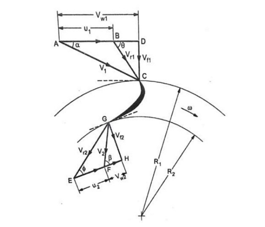
Index 1 refers to inlet flow parameters. Similarly, index 2 indicates parameters related to outer flow.
Uniform Velocity of Inlet and Outlet:
In this triangle, the uniform velocities of inlet and outlet are calculated by:
and
where
and
Work Done:
The work done by Francis turbine per unit weight of water can be calculated by
You can find the parameters in the velocity triangle.
Discharge of Turbine:
The water flow at the inlet or discharge of the turbine can be calculated by
or
where
, , , ,and
.
Efficiencies in Francis turbine:
Francis turbines have three main efficiencies that should be considered. They are:
- Mechanical efficiency
- Hydraulic efficiency
- Overall Efficiency
In what follows, these efficiencies are explained briefly.
Mechanical Efficiency:
The first efficiency in the Francis turbine is mechanical efficiency, which is defined as the ratio of actual available work at the turbine to the energy exposed to the wheel. In other words, mechanical efficiency can be calculated by
or
.Hydraulic Efficiency:
Another important efficiency is hydraulic efficiency, which is defined as the ratio of work done on the wheel to the water energy head provided to the turbine.
The hydraulic efficiency can be calculated by
or
which means
where
Overall Efficiency:
The overall efficiency is defined as the ratio of power generated by the turbine to the energy provided to the turbine. In other words:
or
.
So, now you know everything you needed to know about the Francis turbine. If you have experience with any other types of turbines, share your thoughts with us in the comment section. Feel free to sign up on our website if you want our experts to answer your most complicated questions regarding this field.
Download Francis turbine PDF
Buy Equipment or Ask for a Service
By using Linquip RFQ Service, you can expect to receive quotations from various suppliers across multiple industries and regions.
Click Here to Request a Quotation From Suppliers and Service Providers
Read More on Linquip
- Beginner’s Guide: The Difference Between Gas Turbine and Gas Engine
- Gas Turbine Type : Overview of Types and Profitable Applications
- What is Propeller Turbine? Types and Working Principles
- Differences between Pelton, Francis, and Kaplan Turbine
- What is Hydrokinetic Turbines? Working Principles and Output Power
- Rotor & Stator Blades Gas Turbine for Sale
- Combustion Components Gas Turbine for Sale
- Hot Gas Path Components Gas Turbine for Sale
- 6B.03 Gas Turbine for Sale
- GE 7FA.03 Unit Rotor 7FA.03 for Sale
- Efficiency of Wind Turbines
- The 8 Best Home Wind Turbines in 2022
- How Does a Steam Turbine Work? A Simple Descriptive Guide
- Steam Turbine Efficiency: Complete Explanation
- What is Turgo Turbine and How does it Work?
- Types of Turbines: Classifications and Types
- Types of Wind Turbines: The Quick and Easy Intro
- Gas Turbine Parts: Fast Basic Guide about Components



A very resourceful expose on Francis Turbines
Thanks for visiting our website and leaving your comment, NSISUK! You are encouraged to visit Linquip Tech News, where you can find similar posts.
Good
Thanks for visiting our website and leaving your comment, Amit! We hope to hear from you again in our other posts.
Could you give me the equations?
Thanks for visiting our website, Aria! You can copy and paste formulas from the post. You can also have the PDF format of the website at the end of the post.
Hi
Is good information.
Your kind words are much appreciated, Saeid! It was a pleasure having you visit us.