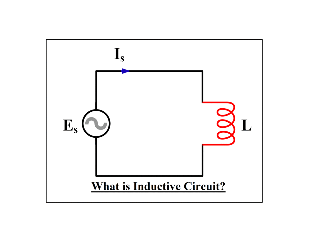
What is an inductive circuit, and how does it work? A Pure inductive circuit is one in which the only quantity in the circuit is inductance (L), with no other components such as resistance or capacitance. The current in this type of circuit lags behind the voltage by 90 degrees. Inductive Reactance is the resistance to current flow via an AC inductor, and it is proportional to the supply frequency.
What is an Inductive Circuit?
An inductor is a coil that stores electrical energy in the magnetic field as current passes through it. The inductor is composed of wire that has been wrapped into a coil. When the current flowing through the inductor varies, the time-varying magnetic field produces an EMF that obstructs the current flow. Henry is the unit of measurement for inductance. The inductive reactance is defined as the resistance to current flow. Visit here to know an inductive circuit fundamentally.
Explanation of an Inductive Circuit
The following figure represents a circuit with pure inductance:
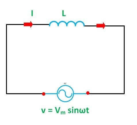
Let’s say the circuit’s alternating voltage is given by the equation:
V={V}_{m}sin(\omega t)
As a result, an alternating current I passes through the inductance, causing an EMF to be generated. The produced emf can be calculated by e=-L di/dt.
The circuit’s induced emf is equal to and opposite to the applied voltage. As a result, the equation becomes v=-e. When we change the value of e in the above equation, we get the following equation:
di=\frac{{V}_{m}}{L}sin(\omega t)dt
By integrating both sides of the above equation, we will get,
i=\frac{{V}_{m}}{L}sin(\omega t-\pi /2)
where XL = ωL is the opposition provided by a pure inductance to the flow of alternating current, also known as inductive reactance. When sin (ωt – π/2) = 1, the value of current will be at its highest. Therefore, Im=Vm/XL.
AC Inductance and Inductive Reactance
Inductors and chokes are made up of coils or loops of wire that are wound around a hollow tube former (air cored) or a ferromagnetic material (iron cored) to boost their inductive value.
When a voltage is applied across the terminals of an inductor, a magnetic field is formed, which stores the energy of the inductor. The rate of growth of the current flowing through the inductor is controlled by the inductor’s own self-induced or back EMF value, which is not instantaneous. The back EMF voltage VL of an inductor coil is proportional to the rate of change of the current flowing through it.
When the self-induced back EMF has decayed to zero, this current will continue to rise until it achieves its maximum steady state condition, which is roughly five time constants. A steady state current is flowing through the coil at this stage, and no further back EMF is created to fight the current flow. As a result, the coil behaves more like a short circuit, enabling maximum current to flow through it.
The flow of current through an inductor behaves substantially differently in an alternating current circuit with an AC inductance than it does in a steady state DC voltage. In an AC circuit, the resistance to current flowing through the coils windings is determined not only by the coil’s inductance but also by the frequency of the applied voltage waveform as it fluctuates from positive to negative values.
The AC Resistance of a coil in an AC circuit determines the real opposition to the current passing through it, and this AC resistance is represented by a complex number. However, the term Reactance is used to distinguish a DC resistance value from an AC resistance value, which is also known as Impedance.
Reactance, like resistance, is measured in Ohms but is denoted by the letter “X” to distinguish it from purely resistive “R” values. Because the component in the problem is an inductor, the reactance of an inductor is known as Inductive Reactance, (XL), and is measured in Ohms. The XL=2πfL formula can be used to calculate its value.
Where XL is the Inductive Reactance in Ohms, π (pi) is a numeric constant of 3.142, f is Frequency in Hertz, and L is Inductance in Henries, (H). We can also define inductive reactance in radians (XL= ωL), where Omega, ω equals 2πƒ.
When a sinusoidal voltage is supplied to an inductive coil, the back EMF opposes the rise and fall of the current flowing through it, and in a completely inductive coil with no resistance or losses, this impedance (which might be a complex quantity) equals the inductive reactance. Also, because reactance has both a magnitude and a direction, it is represented by a vector (angle). Consider the following circuit:
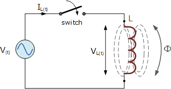
A pure inductance of L Henries (H) is connected across a sinusoidal voltage generated by the formula V(t)= Vmax sin(ωt) in the basic circuit above. This sinusoidal voltage causes a current to flow and rise from zero to its maximum value when the switch is closed. This increase or decrease in current will create a magnetic field within the coil, which will resist or limit the current change.
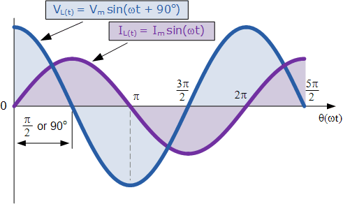
However, the voltage changes polarity before the current reaches its maximum value, as it would in a DC circuit, causing the current to shift direction. The self-induced reverse EMF in the coil delays the change in the other direction once again, and in a circuit with only pure inductance, the current is delayed by 90o.
The applied voltage achieves its maximum positive value a quarter (1/4f) of a cycle before the current does; in other words, a voltage applied to a purely inductive circuit “LEADS” the current by a quarter (1/4) of a cycle or 90o, as shown below.
This effect can also be visualized using a phasor diagram, in which the voltage “LEADS” the current by 90o in a purely inductive connection. However, if we use the voltage as a reference, we can say that the current “LAGS” the voltage by one quarter of a cycle (90o), as illustrated in the vector diagram below.
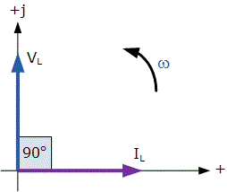
VL “leads” IL by 90o for a pure inductor circuit, alternatively we can say that IL “lags” VL by 90o.
There are a variety of ways to recall the phase connection between the voltage and current flowing through a pure inductor circuit, but one of the easiest is to utilize the mnemonic term “ELI”. In an AC inductance, ELI stands for Electromotive force first, L before the current I. In other words, voltage before current in an inductor, E, L, I equals “ELI,” and this statement always remains true for a pure inductor circuit, regardless of phase angle.
Phasor Diagram and Power Curve of Inductive Circuit
In a pure inductive AC circuit, the current is 90 degrees behind the voltage. A purely inductive circuit’s waveform, power curve, and phasor diagram are presented below.
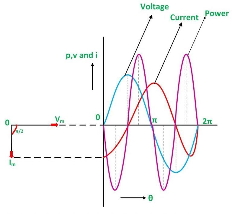
Blue, red, and pink colors represent the voltage, current, and power waveforms, respectively. When the voltage and current are at their maximum positive value, the power is also positive; conversely, when the voltage and current are at their lowest negative value, the power is also negative. The phase difference between voltage and current is the reason behind this.
The current value changes when the voltage is reduced. When the current is at its maximum or peak, the voltage will be zero at that point in time, and the voltage and current will be 90 degrees out of phase.
On the left-hand side of the waveform, the phasor diagram shows the current (Im) lagging voltage (Vm) by an angle of π/2.
Power in Pure Inductive Circuit
The inductive circuit’s instantaneous power is given by
P=\frac{{V}_{m}}{\sqrt{2}}\frac{{I}_{m}}{\sqrt{2}}sin(2 \omega t)
Or P=0
As a result, with a purely inductive connection, the average power consumed is zero. Because the negative and positive loops are under the same power curve, the average power in one alteration, i.e. in a half cycle, is zero.
During the first quarter cycle of a purely inductive circuit, the power supplied by the source is stored in the magnetic field created around the coil. The magnetic field weakens in the following quarter cycle, and the power accumulated in the first quarter cycle is restored to the source. Every cycle, this process repeats itself, resulting in no power consumption in the circuit.
Buy Equipment or Ask for a Service
By using Linquip RFQ Service, you can expect to receive quotations from various suppliers across multiple industries and regions.
Click Here to Request a Quotation From Suppliers and Service Providers
Read More In Linquip
- What is Resistive Circuit? Example & Diagram
- What is Linear Circuit? Example & Diagram
- What is Capacitive Circuit? Formula & Function
- What is LC Circuit? Formula, Equitation & Diagram
- What is RL Circuit? Formula, Equitation & Diagram
- What is RC Circuit? Formula, Equitation & Diagram
- Types of Resistor: Classification, Application, and Finally Clarification
- What is Parallel Circuit? Definition & Example
- What is Series Circuit? Definition & Example
- What is Closed Circuit? Definition & Example
- What is Short Circuit? A Clear Definition & Protection Guide
- What is Open Circuit? Diagram & Example
- What is Inductive Circuit?
- Difference Between Linear and Nonlinear Circuits
- Types of Electric Circuits: All Classification with Application
- What are the Differences Between Series and Parallel Circuits?
- Types of Electric Circuits: All Classification with Application
- How does a Circuit Breaker Work?
- What is Vacuum Circuit Breakers?
- Difference Between Isolator and Circuit Breaker: Ultimate Guide
- Difference Between Relay and Circuit Breaker: Everything You Need to Know
- Difference between Series and Parallel Circuits | What are they Completely?

