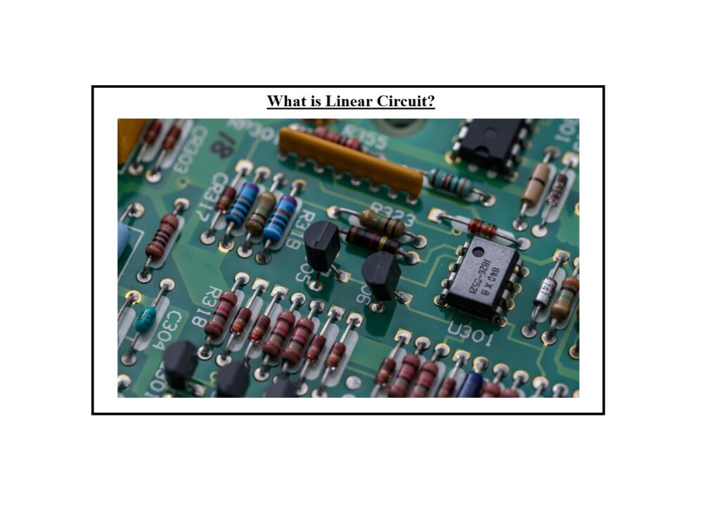
What is a Linear Circuit, and how does it work? A linear circuit is an electronic circuit that follows the principle of superposition. The theorem of superposition can be applied to any linear circuit. When there are multiple independent sources, the voltages and currents generated by each can be calculated separately and then summed algebraically. This avoids the need to create a sequence of loop or node equations, simplifying the calculations.
It is the goal of the Linquip team to provide as much information regarding the linear circuit as possible. Whenever you are looking for information regarding this type of electrical equipment, Linquip will be your best resource. We at Linquip are always available if you need any help with circuits or if you have any questions or concerns about them. The first thing we have to suggest you do is to read Linquip’s article titled “What Is Electrical?” before moving on to the next step. I hope you will find this page to be helpful in understanding industrial electrical equipment as a whole.
Using the Linquip platform to its full potential requires becoming a Linquip Expert. Registering for an expert account with Linquip can be very beneficial for you since it enables you to demonstrate your expertise in the area of industrial equipment in a way that matches the industry’s requirements. Are you interested in contributing to the Linquip website as a guest writer? Linquip’s Guest Posting feature allows you to publish your content directly on our website.
What is a Linear Circuit?
Because the output voltage and current of such a circuit are linear functions of the input voltage and current, it is called a linear circuit. The principle is illustrated in the diagram below.
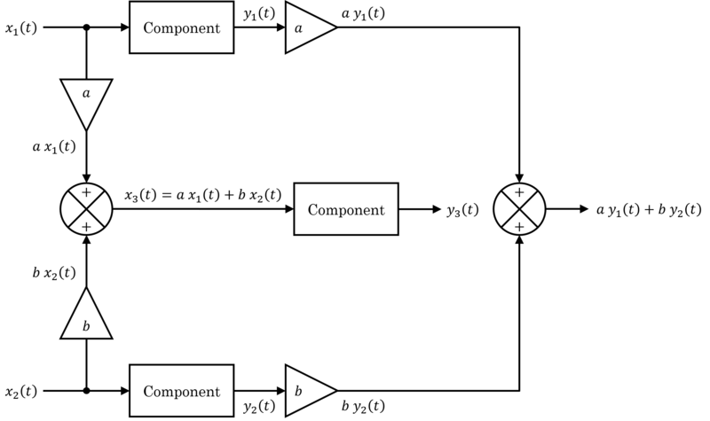
When a sinusoidal input voltage or current of frequency f is applied to any steady-state part of the circuit (the current through any component, or the voltage between any two points), an alternate definition of linearity is that any steady-state output of the circuit (the current through any component, or the voltage between any two points) is also sinusoidal with frequency f. The term linear time-invariant refers to a linear circuit with constant component values (LTI).
A linear circuit is one in which the values of electrical components (such as resistance, capacitance, inductance, gain, and so on) do not change when the voltage or current in the circuit increases. Linear circuits are useful because they can amplify and process electronic signals without introducing any distortion. A sound system is an example of electronic equipment that uses linear circuits. Visit here to see the principle of a linear circuit.
Alternate Definition
The defining equation of linearity, the superposition principle, is identical to two qualities, additivity, and homogeneity, which are usually utilized as an alternative definition.
F({x}_{1}+{x}_{2})=F({x}_{1})+F({x}_{2})
F(hx)=hF(x)
A linear circuit is one in which (1) the output of a sum of two signals is identical to the sum of the outputs when the two signals are applied individually, and (2) scaling the input signal x(t) by a factor h scales the output signal F(x(t)).
Significance of a Linear Circuit
Linear circuits are useful because they can process analog signals without intermodulation distortion. This means that distinct frequencies in the signal remain separate and do not mix, resulting in the creation of new frequencies (heterodynes).
They’re also less difficult to comprehend and analyze. Linear circuits are governed by linear differential equations and may be investigated using strong mathematical frequency domain techniques such as Fourier analysis and the Laplace transform because they obey the superposition principle.
These also provide a visual representation of the circuit’s qualitative behavior, with terminologies like gain, resonant frequency, phase shift, bandwidth, Q factor, poles, and zeros used to describe it. A linear circuit can often be analyzed by hand with the aid of a scientific calculator.
Non-linear circuits, on the other hand, rarely have closed-form solutions. If precise results are desired, they must be examined using approximate numerical approaches by electrical circuit simulation computer programs such as SPICE. A single number can specify the behavior of linear circuit parts like resistors, capacitors, and inductors (resistance, capacitance, inductance, respectively).
A nonlinear element’s behavior is determined by its detailed transfer function, which can be represented by a curved line on a graph. As a result, stating the characteristics of a nonlinear circuit necessitates more information than specifying the features of a linear circuit.
Electronic manufacturing has a separate category for “linear” circuits and systems. Transistor and integrated circuit manufacturers frequently separate their product lines into ‘linear’ and ‘digital’ categories. The term “linear” here refers to “analog” integrated circuits, such as op-amps, audio amplifiers, and active filters, as well as a number of signal processing circuits that perform non-linear analog functions, such as logarithmic amplifiers, analog multipliers, and peak detectors.
Filtering Process in a Linear Circuit
In linear circuits, there is one crucial action that is frequently used and must be shown on block diagrams. When there are multiple signals present, filtering implies separating one band of frequencies from the others.
For example, if a mixed signal is used to run a loudspeaker or headphones, you could wish to filter it such that it only contained the frequencies that your ear would detect. You might want to filter a mixed signal to remove the power-line frequencies and leave just the higher frequencies. You might also wish to filter a mixed signal so that all of the higher frequencies are eliminated.
Principle of Filtering
A filter is an electrical circuit that selectively acts on one or a range of frequencies, either passing or rejecting that frequency or range.
We call a filter a low-pass filter when it only passes the lower range of the frequencies given to it. The figure below shows a typical graph of output plotted versus input for such a filter. This type of filter can be used in an audio amplifier to prevent undesired noises from reaching a loudspeaker at higher frequencies (ultrasonic frequencies).

The graph presenting the response of a high-pass filter, which rejects the lower frequencies of a mixture and passes only the higher frequencies, can also be shown. This can be used in an audio amplifier to prevent undesirable low-frequency disturbances from influencing the loudspeakers (for example, rumbling from a turntable).
The band-pass filter, on the other hand, rejects both the highest and lowest frequencies while passing just a range of frequencies in between. This type of band-pass action is performed by a radio tuner in order to receive only one station rather than a jumbled mix of all the signals it can pick up.
Linear Circuit Elements
The components in an electrical circuit that have a linear relationship between the current input and the voltage output are referred to as linear circuit elements. Examples of elements with linear circuits are:
- Resistors
- Capacitors
- Inductors
- Transformers
An analysis of elements is required to gain a better understanding of linear circuit elements.
Resistors
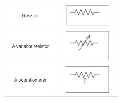
A resistor is a device that restricts the flow of an electric current, causing energy conversion. When electricity passes through a light bulb, for example, it is transformed into a new kind of energy, such as heat and/or light. An element’s resistance is measured in ohms Ω.
The resistance in a circuit is calculated as follows:
R=\rho \frac{L}{A}
Where R stands for resistance, ρ for resistivity, L for wire length, and A for wire cross-sectional area.
Capacitors
A capacitor is an electrical device that consists of two conducting materials (plates) separated by an insulator (dielectric). It stores electric energy via an electric field. When the capacitor is linked to a battery, an electric field is created, causing positive electric charges to accumulate on one plate and negative electric charges to accumulate on the other.
The process of storing energy in the electrical field of a capacitor is called charging, and the process of removing energy is termed discharging. Capacitance is the amount of electrical energy stored in a capacitor and is measured in farads F. One farad equals one coulomb per unit volt, denoted as 1 C/V.
The difference between a capacitor and a battery is that a capacitor stores electrical energy and releases it slowly, whereas a battery stores chemical energy and releases it gradually.
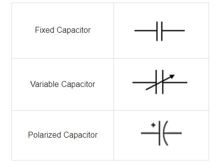
A capacitor’s various symbols are included in the figure below.
Inductors
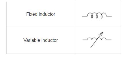
Inductors are electronic devices that store electric energy using a magnetic field. A coil or a wire in loop form is the most basic type of inductor, with inductance proportional to the number of loops in the wire. In addition, the inductance is affected by the wire’s material and the loop’s radius.
Only the air core can result in the least inductance given a specified number of turns and radius size. Wood, glass, and plastic are dielectric materials that fulfill the same purpose as air. These materials aid in the inductor winding process. The total inductance is increased by the donut form of the windings as well as ferromagnetic materials such as iron. Inductance is the amount of energy that an inductor can store. It is measured in Henry H.
Transformers
This is an instrument that uses electromagnetic induction to change the state of energy from one level to another. It’s typically used to raise or lower AC voltages in electric-powered applications.
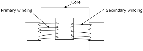
When the primary side of the transformer’s current varies, a fluctuating magnetic flux is formed on its core, which spreads out in the form of magnetic fields to the secondary windings of the transformer.
A transformer’s operation is based on Faraday’s law of electromagnetic induction. The law asserts that the EMF produced in a conductor is directly proportional to the rate of change of the flux connecting with respect to time.
A transformer is made up of three basic components:
- Primary winding
- Magnetic core
- Secondary winding
Additional Parts of a Linear Circuit
Electromagnetic Devices
Electromagnetism is a widely utilized concept in technology, with applications in motors, generators, and electric bells. In a doorbell, for example, the electromagnetic component attracts a clapper, which then strikes the bell, causing it to ring.
Controllers
Controllers are electronic devices that receive electronic signals from a process’s measured variable and compare the value to a control set point. It compares and correlates functions using digital algorithms.
Sensors
Sensors are utilized to determine current, which varies constantly to offer control feedback. It is feasible to produce a smooth and accurate converter function by sensing current. Current sensors are essential in converters so that data from parallel or multiphase converters may be transferred conveniently.
Filters
Electronic filters are also used to remove unwanted frequencies from signals during processing. They’re analog circuits, and they can be active or passive.
Download What is Linear Circuit? PDF
By clicking on the link provided below, you can download the entire contents of this article as a PDF file.
Buy Equipment or Ask for a Service
By using Linquip RFQ Service, you can expect to receive quotations from various suppliers across multiple industries and regions.
Click Here to Request a Quotation From Suppliers and Service Providers
Read More In Linquip
- Types of Electric Circuits: All Classification with Application
- How does a Circuit Breaker Work?
- What is RC Circuit?
- What is RLC Circuit
- What is Capacitive Circuit?
- Types of Resistor: Classification, Application, and Finally Clarification
- What is Parallel Circuit? Definition & Example
- What is Series Circuit? Definition & Example
- What is Closed Circuit? Definition & Example
- What is Short Circuit? A Clear Definition & Protection Guide
- Difference Between Linear and Nonlinear Circuits
- What are the Differences Between Series and Parallel Circuits?
- The 8 Best Circuit Breaker Locators in 2022
- What is LC Circuit? Formula, Equitation & Diagram
- What is Open Circuit? Diagram & Example
- What is Inductive Circuit?
- What is AC Circuit and Its Characterization?
- Circuit Breaker vs Fuse- What are the Main Differences?
- How does a Circuit Breaker Work?
- What is the Equivalent Circuit of Transformer?
- Potentiometer Connection, Working, Circuit Diagram, & Wiring Guide
- Difference Between Relay and Circuit Breaker: Everything You Need to Know
- Difference Between Isolator and Circuit Breaker: Ultimate Guide
- Piezoelectric Transducer and Its Impressive Applications in Electric Circuits
- What is Vacuum Circuit Breakers?
- Types of Circuit Breaker: A Basic Guide to Know Different Classifications

