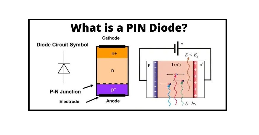
A PIN diode is an advancement of the standard PN combination diode. It is a 3-layer instrument in which an intrinsic section i.e. undoped semiconductor is compressed between N and P regions. Therefore, making it a PIN diode. The intrinsic region performs as the high resistance section. Based on this, the magnitude of the electric flux also becomes high. This resultantly improves the electron and hole pair production in the region. As a result, it allows the performance of the weak input signal.
What is a PIN Diode?
Definition
The diode in which the intrinsic part with a large resistivity is pressured between the P and N regions of a semiconductor substance such type of diode is introduced as the PIN diode. The high resistive section of the intrinsic part presents the large electric field between the N and P regions. The electric flux induces due to the movement of the electrons and the holes. The direction of the electric flux is from the N-region to the P-region.
The large electric field produces high electron-hole pairs due to which the diode process even for the low signals. The PIN diode is a form of photodetector employed for transforming light energy into electrical output.
It is a kind of photodetector that can convert light power into its electrical form because of the presence of the intrinsic layer. Along with offering large resistance, a PIN diode also possesses a smaller value of capacitance.
As with the insertion of the intrinsic layer, the gap between N and P regions increases. From the above definition, it is obvious that the distance and capacitance are inversely proportional. Therefore, with the reduction in the distance, the capacitance increases.
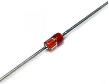
The intrinsic region between the P and N sections increases the gap between them. The width of the section is inversely related to their capacitance. If the separation between the N and P sections increases, their capacitance drops. This property of the diode improves its response time and makes the diode appropriate for operations like microwave cases.
History
The PIN diode is an alteration of the PN combination for special systems. After the PN-combination diode was constructed in the year 1940s, the diode was first used as a high-energy rectifier, low-frequency during the year 1952. Using an intrinsic section can considerably increase the breakdown voltage in the case of high-voltage. This intrinsic section also provides exciting characteristics when the instrument operates at high frequencies in the case of microwave and radio waves.
A PIN diode is one type of electronic instrument with an undoped, large intrinsic semiconductor section between P-type and N-type semiconductors. These sections are typically heavily doped as they are applied for Ohmic contacts. The larger intrinsic section is indifferent to an ordinary n-p diode. This section makes the diode an inappropriate rectifier but it makes it suitable for attenuators, fast switches, photodetectors, and high-voltage energy electronics applications.
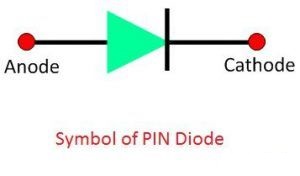
Symbol of PIN Diode
The term PIN diode obtains its expression from the fact that contains three main layers. Rather than just including a P-type and an N-type region, it has three sections such as
- P-type layer
- Intrinsic layer
- N-type layer
The symbolic representation of the diode is provided in the figure below. The cathode and anode are the two terminals of the PIN diode. The cathode is the negative terminal and the anode represents their positive terminals.
PIN Diode Structure
The diode includes the N-region and P-region which is divided by the intrinsic section that has a semiconductor substance. In the P-section the hole is the main charge carrier whereas in the n-section the electron is the main charge carrier. The intrinsic part has no free charge carrier. It performs as an insulator between the n and the p sections. The intrinsic region has a large resistance which blocks the flow of electrons to pass across it.

Construction of PIN Diode
A PIN diode is a 3-layer instrument that includes n-region, p-region, and intrinsic sections. The n-region is created when the pentavalent impurity is covered in the semiconductor area. The p-region is created by forming a trivalent impurity to the semiconductor part. The region of an intrinsic material is nothing but the undoped semiconductor substance. The figure below demonstrates the constructional overview of a PIN diode.
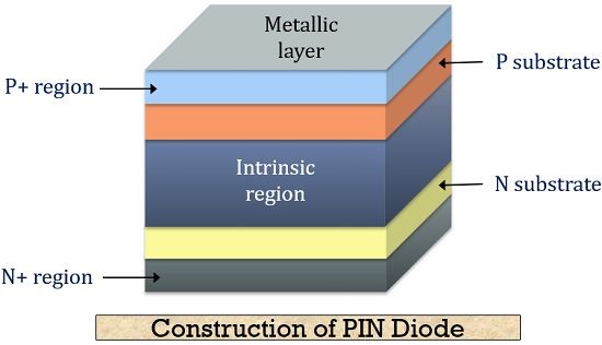
A PIN diode can be constructed by two methods, i.e. either by mesa structure or planar structure.
In the case of the mesa type, the sections of semiconductor which are previously covered are developed (grown) on the intrinsic section. Thereby producing a PIN diode.
In the case of the planar type, a thin (narrow) epitaxial section is imposed on the intrinsic part in order to create the P-region. Similarly, the N-region is also formed on another section of the substrate. The intrinsic section presents a very large resistivity of the order of 0.1 Ω-m.
The gap between the N & P sections contains no charge carriers. This is due to the fact that any holes or electrons merge as the depletion section of the diode has no charge carriers it operates as an insulator. The depletion area is available within a PIN diode, but if the PIN diode is in the forward-biased type, then the carriers come into the depletion area and as the two carrier forms get together, the flow of current will begin.
Once the PIN diode is configured in the forward-biased form, the charge carriers are much larger than the rate of the intrinsic carrier’s attention. Because of this reason, the electric flux and the high rating injection level extend deeply into the section. This electric flux assists in speeding up the sliding of charge carriers from P to N areas, which consequences in faster performance of the PIN diode, making it a suitable instrument for high-frequency applications.
Working Principle of PIN Diode
The working principle of the PIN diode is similar to other typical diodes. Once the diode is unbiased, its charge carrier will distribute. The word distribution means the charge carriers of the depletion area try to transmit to their basic section. The procedure of distribution resumes continually until the charges become equivalent in the depletion area.
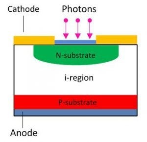
Consider the N and intrinsic layers make the depletion area. The distribution of the electron and hole through the region produces the depletion section within the NI section. The narrow depletion layer induces through the n-region, and the thick depletion area of opposite polarity induces through the intrinsic part.
A PIN diode is approximately similar to a standard PN combination system; however, the main difference is the presence of an intrinsic section. This section is nothing but serves as the depletion area between N and P regions.

While no external potential is presented to the diode, the carriers distribute through the junction due to the concentration gradient. Therefore, it can create a depletion section at the NI junction. Although, the thickness is larger on the intrinsic region as compared to the n-region. This is since the basic level of the N-region is very much greater than the intrinsic section. As we already know that the intrinsic section is an undoped semiconductor material. There are two main conditions in the pin diode bias state: Forward and Reverse biased conditions. Click here to see the working principle of a PIN diode completely.
Forward Biased Condition
In case a forward voltage is supplied to the diode, the charge carriers from the N and P regions are entered into the intrinsic section. This is so because induced forward potential decreases the depletion width. Because of this, the resistance provided by the instrument in no biased condition starts reducing due to forward biasing. Therefore, as the forward voltage is raised, a higher number of charge carriers gets injected into the intrinsic section.
Thereby, generating a large current across the device and resultantly reducing the resistance. As a result, it is said that the PIN diode behaves like a variable resistance instrument in a forward-biased condition.
Forward Biased PIN Diode
When the diode is in the forward-biased condition, the charges are regularly injected into the intrinsic section from the P and N regions. This drops the forward resistance of the diode, and it can perform as a variable resistance.
The charge carrier injected from P and N sections into the intrinsic part is not quickly combined into the intrinsic section. The finite quantity of charge kept in the intrinsic section reduces the resistivity.
Let the Q be the quantity of charge kept in the depletion section. The τ is the time utilized for the recombination of the charges. The quantity of the charges kept in the intrinsic section is based on the recombination time. The forward current begins flowing across the intrinsic region.
where IF is the forward current in the intrinsic region and τ is the recombination time.
The resistance of the current in the forward-biased condition is inversely related to the charge Q kept in the intrinsic section as the following:
where ω is the width region, μ is the electron mobility, and μ0 is the hole mobility.
From the previous equations, we get
The above equation demonstrates that the resistance of the intrinsic section is based on the width of the region.
Reverse Biased Condition
When the reverse bias voltage is used in the device, the depletion gap starts increasing. Once the reverse voltage is increased, the width of the depletion section improves as far as whole mobile carriers are swept away from the intrinsic section. This special voltage is introduced as the swept out voltage. Its typical value is -2V.
The device performs as a capacitor with a reverse biased voltage. Here N and P regions serve as the two parallel surfaces of the capacitor. In the case of high reverse biased conditions, a thin depletion section is noticed in the P section.
Reversed Biased PIN Diode
Once the reverse voltage is applied through the diode, the width of the depletion section increases. The thickness of the section increases until the whole mobile charge carrier of the intrinsic section is swept away from it. The reverse voltage needs to remove the complete charge carrier from the intrinsic region.
In the reversed biased condition, the diode behaves like a capacitor. When the N and P regions operate as the negative and positive plates of the capacitor, the intrinsic section is the insulator between these plates. The potential of this capacitor can be obtained as
where A is the junction diode and w is the thickness of the intrinsic region.
The main frequency at which the effect begins is presented as
Where ε is the constant of silicon dielectric.
Characteristics of PIN Diode
Low Capacitance
As we already explained that a PIN diode provides a lower value of capacitance because of the larger distance between the P and N sections. When just a low reverse potential is performed, the depletion section gets completely depleted. As the depletion process ends, the capacitance now does not provide modification with the applied potential because of the presence of a low amount of charge in the intrinsic section.
High Breakdown Voltage
Because of the presence of the intrinsic part, the PIN diode shows a higher value of breakdown voltage. This is because a greater voltage is needed in order to destroy the thick depletion section.
Sensitive to Photodetection
The depletion section is responsible for producing energy when radiation contacts its surface. The existence of an intrinsic section improves the area for radiation absorption. Therefore, these are broadly employed as photodetectors.
Storage of Carriers
This is an important feature of a PIN diode. The intrinsic section increases the area for carrier storage. The saved charge in the depletion section is responsible for the value of the current flowing across the circuit. When the forward biasing condition is presented to the system, then, in this case, the instrument provides variable resistance features. The resistance changes with the supplied input voltage. Therefore, it does not generate distortion or rectification.
Equivalent Circuit of PIN Diode
Due to the unique structure of the diodes, their equivalent circuits are typically different and practically more simplified than those associated with PIN diodes manufactured using conventional techniques. These equivalent circuits for diodes are presented in the following figure.
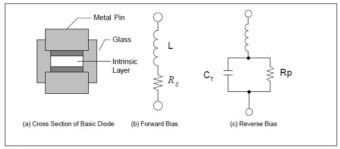
Due to the absence of small ribbons or wires, the package capacitance is fully in parallel arrangement with the PIN chip, there is virtually no internal system of inductance to notice as is the case with normal PIN diodes. The complete faced bond obtained between the silicon chip and the metallic PINs, connected with the relatively great chip region, results in negligible contact resistance. Thus, the “residual series resistance” in normal devices, is for all practical cases, nonexistent in special PIN diodes.
Any self-inductance provided by the PIN diode is external to the diode’s potential and is similar to that of a conducting cylinder including the same physical outline as the diode chip and PINs. Evaluations using self-inductance formulas show the package inductance to be in the range of 0.10 nH for all PIN diode types. More self-inductance can be provided by any lead connected to the package.
Thus, at frequencies smaller than 1 GHz, the system parasitic influences are normally negligible. At higher values, the total dimensions and materials of the diode package must be noticed in both the diode selection and the circuit design.
Applications of PIN Diode
High Voltage Rectifier: It is employed in different applications as a high voltage rectifier. The diode has a high intrinsic section between the N and P regions which can tolerate the large reverse voltage. The PIN diode is able to bear great reverse voltage because of the intrinsic layer. This leads to an improvement in the breakdown voltage of the device. As a result, due to this, the diode allows the rectification of large input voltage.
Photo-detector: The PIN diode is also applied for transforming the absorbed light energy into electrical output. The diode has a great depletion region which improves its function by increasing the volume of light transformation. The existence of an intrinsic section between the P and N regions increases the possibility of radiation absorption. With the increased radiation absorption section, the efficiency of the instrument to generate the electrical energy also increases. Therefore, it can be employed as a photodiode.
As a radio frequency switch: The intrinsic section isolates the N and P parts of the diode due to which capacitance reduces. The capacitance of the instrument should almost negligible in order to use it as a switch.
PIN diodes provide a faster response time. Because of this, they are broadly employed in microwave applications.
The PIN diode is also the most suitable diode for low voltage cases.
Key Terms Related to PIN Diode
Swept-out voltage: It happens when the reverse voltage is applied at which the charge carriers get totally swept away from the depletion section.
Response time: It is the time taken by the instrument to provide variation from one state to another. Or we can say, the time taken by the instrument varies from conducting to non-conducting level or vice-versa.
Buy Equipment or Ask for a Service
By using Linquip RFQ Service, you can expect to receive quotations from various suppliers across multiple industries and regions.
Click Here to Request a Quotation From Suppliers and Service Providers
Read More In Linquip:
- Top USA and International Semiconductor Manufacturers in 2022
- Differences Between P-Type and N-Type Semiconductors

