What is Pull-up and Pull-down Resistors – The inputs of digital gates need to be appropriately biased using pull-up and pull-down resistors to prevent them from drifting around arbitrarily when no input condition is present.
On the Linquip website, among the many options available to you, you will find all the information you need to know about the Resistors, as well as information regarding this marketplace. You can count on Linquip to provide you with as much general and reliable information about this topic, whether you’re a professional or a customer looking for a proper company. We recommend you review a list of all Resistor Products available in Linquip. You can also be encouraged to visit Resistor for Sale and find the most suitable device based on your applications and demands.
What Are Pull-up Resistors?
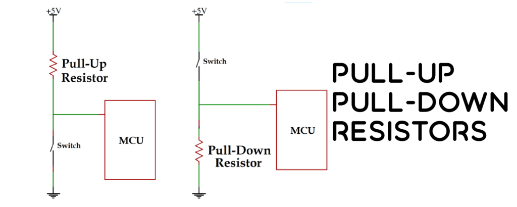
In logic circuits, pull-up resistors are employed to maintain a consistent logical level at a pin. The three logic states of a digital logic circuit are high, low, and floating, and they are named accordingly (or high impedance). When the pin is not connected to a high or low logic level, but is instead left “floating,” the result is a high-impedance condition. A microcontroller’s unused input pin is a perfect example of this. It is in a logic state between high and low, and the microcontroller may read it as a logical high or low depending on its status. As can be seen in the following image, pull-up resistors are employed to alleviate the problem for the microcontroller by forcing the value to the logical high position.

The pull-up resistor prevents the MCU input from floating when the switch is open; when the switch is closed, the input is pushed down to a logical low.
Pull-up resistors are essentially fixed-value resistors linked between the voltage supply (usually +5 V, +3.3 V, or +2.5 V) and the corresponding pin, specifying the input or output voltage in the absence of a driving signal. The value of a pull-up resistor is typically 4.7 k but can be adjusted as needed.
What Are Pull-down Resistors?
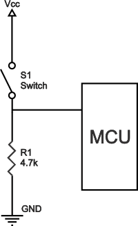
Similar to pull-up resistors, pull-down resistors are used to set a pin to a logical low. They are wired to the device’s ground and the corresponding pin. The following diagram depicts a digital circuit with a pull-down resistor.

Here we see a pushbutton switch wired in series with the power line and a microcontroller input. When the switch is closed, the microcontroller’s input has a logical high value; however, when the switch is open, the input voltage is pulled down to ground (a logical zero value), avoiding an undefinable condition. It is important that the pull-down resistor’s resistance be greater than the impedance of the logic circuit; otherwise, the input voltage at the pin will always be a logical low, regardless of the position of the switch.
Pull-up and Pull-down Resistor Values
The pull-up (or pull-down) resistor’s ideal value is constrained by two considerations. Dissipation of electricity is the primary contributor. When the switch is closed, if the pull-up resistor’s resistance value is too low, a large current will flow through it, warming the device and wasting power. Strong pull-ups should be avoided wherever possible to save power usage. Second, there’s the open-switch pin voltage. When the switch is open, the input voltage might drop dangerously low if the pull-up resistance value is too high and the input pin has a high leakage current. Weak pull-ups are the result of a lack of strength. Impedance of the input pin, which is closely connected to leakage current, determines the real value of the pull-resistance.
As a rule of thumb, the resistor’s value should be at least 10 times lower than the input pin’s impedance. An average pull-up resistor value in 5 V bipolar logic families is between 1 and 5 k. The usual pull-up resistor value for use with switches and resistive sensors is 1-10 k. For switches, 4.7 k is a safe default value to use if you’re unsure what to set it to. Input leakage current is very low in CMOS families and other digital circuits, allowing for significantly greater resistance values of 10 k to 1 M. One drawback of adopting a higher resistance value is a diminished sensitivity of the input pin to voltage fluctuations. This is due to the RC circuit formed by the pull-up resistor and the sum capacitance of the pins and wires at the switching node. The time required for the capacitance to charge and discharge increases as the product of R and C is bigger, making the circuit run more slowly. Pin switching speeds in high-speed circuits may be impeded by the presence of a large pull-up resistor.
Typical Application of Pull-up and Pull-down Resistors
When connecting a switch or other input to a microcontroller or other digital gates, pull-up and pull-down resistors are common components. Fewer external components are required because of the programmable pull-up and/or pull-down resistors present in the majority of microcontrollers. These microcontrollers can have a switch connected to them directly. In most cases, pull-up resistors are preferred over pull-down resistors; nevertheless, some microcontroller families include both types.
As the first step in the analog-to-digital conversion of a resistive sensor’s voltage-based output signal, they are frequently employed to supply a regulated current to the sensor.
Another use case is the I2C protocol bus, which utilizes pull-up resistors to convert a single pin to either an input or an output. Without being attached to a bus, the pin exists in a high-impedance free-floating condition. A pull-down resistor is used on an output to ensure a consistent and predictable impedance.
When connecting logic gates to inputs, a pull-up resistor may be necessary. A resistor can be used to draw an input signal low, and a switch or jumper strap can be used to connect the low input to ground. A device’s setup data, choice selections, and troubleshooting all benefit from this.
Logic outputs can have pull-up resistors connected to them if the logic device is unable to source current on its own, as is the case with open-collector TTL logic devices. The application of these outputs can be as basic as operating a logic bus with numerous devices attached to it, or as complex as performing a wired-OR function in combinational logic.
There may be a separate pull-up resistor device on the same circuit board as the logic components. Embedded control applications can benefit from the reduced number of external components required thanks to the inbuilt, programmable pull-up resistors included in many microcontrollers.
Pull-up resistors have a slower speed as compared to an active current source, and they use more power when the current is pulled through the resistor. For some logic families, the use of pull-up resistors at the inputs might cause problems due to power supply transients, necessitating the use of a separate filtered power source for the pull-ups.
Since the inputs of CMOS logic gates are voltage regulated, pull-down resistors can be employed without risk. Unconnected TTL logic inputs float high and need a significantly smaller pull-down resistor to be forced down. Normal operation for a TTL input at logic “1” assumes a source current of 40 A and a voltage level above 2.4 V, allowing a pull-up resistor of no more than 50 kΩ; normal operation for a TTL input at logic “0” assumes a sink current of 1.6 mA and a voltage level below 0.8 V, requiring a pull-down resistor of less than 500 ohms. Inputs to TTL gates that are not being used draw more power when held low. That’s why pull-up resistors are such a big deal in TTL circuits.
Based on the need to deliver the needed logic level current over the whole working range of temperature and supply voltage, a common pull-up resistor value for 5 VDC bipolar logic families is 1000-5000 Ω. Since the needed leakage current at a logic input is minimal, resistors with significantly greater values, several thousand to a million ohms, can be employed in CMOS and MOS logic.
FAQs about Pull-up and Pull-down Resistors
What are pull-up and down resistors?
For AND and NAND gates, a pull-up resistor is a resistor that is connected to the dc supply voltage, Vcc, to maintain a HIGH input. To maintain the LOW state of the provided input, an OR or NOR gate’s unused input pin is connected to ground (0V) using a pull-down resistor.
What is a pull-up resistor used for?
In a digital logic circuit, a pull-up resistor is a fixed-value resistor connected between a voltage source and a specific pin. Its primary use is in conjunction with switches; while the switch is open, it regulates the voltage between Ground and Vcc.
What is the difference between a pull-up and pull-down circuit?
When a digital pin is connected to a Pull-up resistor, it will always be in the High state, or at the logic level (5V in the example shown above), but when connected to a Pull-Down resistor, it will always be in the Low state (0V).
Conclusion
You may acquire all the details you want about the Resistors and details about this market on the Linquip website, one of the numerous possibilities available to you. Whether you’re a professional or a client seeking for a reputable business, you can rely on Linquip to give you as much basic and trustworthy information on this subject. We advise you to look through the whole range of Resistor Experts and take advice from our professionals. If you need any services required for your product, you can count on Linquip and visit Resistor Services.
Download PDF for What is Pull-up and Pull-down Resistors?
You can download the PDF format of this post from the link provided here.
Buy Equipment or Ask for a Service
By using Linquip RFQ Service, you can expect to receive quotations from various suppliers across multiple industries and regions.
Click Here to Request a Quotation From Suppliers and Service Providers
Read More on Linquip
- Variable Resistor∶ Learn The Basics, Get The Most out of It!
- Mastering Resistance Calculations: A Comprehensive Guide for Electrical Enthusiasts
- A Quick Guide to Resistor Color Code
- A Quick Guide to Resistor Sizes and Packages
- All You Need to Know About Guide to Resistor Values
- What is Braking Resistor? (A Practical Guide)
- What Are Resistors for LED Circuits? (Clear Guide)
- Everything You Need to Know About Variable Resistor Function
- Variable Resistor Symbol։ Everything You Need to Know
- Types of Resistor: Classification, Application, and Finally Clarification
- What is Shunt Resistor? + Function & Applications


