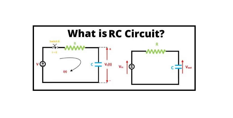
What exactly is an RC Circuit? The RC circuit is made up of a pure resistance R in ohms and a pure capacitance C in Farads. The capacitor stores energy and a resistor connected with it controls the capacitor’s charging and discharging. Camera flashes, pacemakers, and timing circuits all use the RC circuit.
What is RC Circuit?
A resistor-capacitor combination (sometimes called an RC filter or RC network) is a resistor-capacitor circuit. An RC circuit is an electrical circuit that is made up of the passive circuit components of a resistor (R) and a capacitor (C) and is powered by a voltage or current source. An RC circuit, like an RL or RLC circuit, will consume energy due to the inclusion of a resistor in the ideal version of the circuit.
This is in contrast to the ideal version of an LC circuit, which consumes no energy because there is no resistance. Even an LC circuit will waste some energy in actuality due to the non-zero resistance of the components and connecting wires, which is only in the ideal form of the circuit.
RC Circuit Principle
The capacitor, C, charges up through the resistance, R, when a voltage source is applied to an RC circuit. When a signal or voltage, either continuous (DC) or alternating (AC), is applied to any electrical or electronic circuit or system, there is some type of “time-delay” between the input and output terminals.
This delay is commonly referred to as the circuit’s time delay or Time Constant, and it represents the circuit’s time response when a step voltage or signal is applied. The time constant of any electronic circuit or system is mostly determined by the reactive components linked to it, which can be capacitive or inductive. The time constant is measured in Tau – τ.
When a discharged capacitor is exposed to an increasing DC voltage, the capacitor draws a “charging current” and “charges up.” The capacitor begins to discharge in the opposite direction as the voltage is decreased. As capacitors can store electrical energy, they function similarly to small batteries in that they store and release energy on their plates as needed.
Q = CV represents the electrical charge stored on the capacitor’s plates. The charging (storage) and discharging (release) of a capacitor’s energy is never instantaneous; it takes time for the capacitor to charge or discharge to within a specific percentage of its maximum supply value, which is known as the Time Constant (τ). See here to know the principle of an RC circuit completely.
When a resistor is linked in series with a capacitor to form an RC circuit, the capacitor will continuously charge up through the resistor until the voltage across it equals the supply voltage. The time necessary to fully charge the capacitor is approximately 5 time constants or 5T. As a result, a series RC circuit’s transient response is equivalent to 5 time constants.
This transient response time, T, is expressed in seconds as τ= R.C, where R is the resistor value in ohms and C is the capacitor value in Farads. This then serves as the foundation for an RC charging circuit, with 5T standing for “5 x RC.”
RC Charging Circuit
A capacitor (C) in series with a resistor (R) forms an RC Charging Circuit that is connected across a DC battery supply (Vs) via a mechanical switch in the diagram below. When the switch is first closed at time zero, the capacitor progressively charges up through the resistor until the voltage across it reaches the battery’s supply voltage. The charging of the capacitor is depicted in the diagram below.
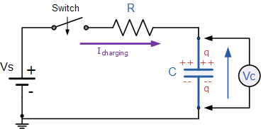
Assume that the capacitor, C, has been totally “discharged” and that the switch, S, is fully open. These are the circuit’s initial conditions, then t = 0, I = 0, and q = 0. When the switch is closed, time starts at t = 0, and current flows into the capacitor through the resistor.
The capacitor appears to be a short circuit to the external circuit at t = 0 because the initial voltage across the capacitor is zero (Vc = 0), and the maximum current flows through the circuit limited only by the resistor R. The voltage drops around the circuit are then calculated using Kirchhoff’s voltage law (KVL) as follows:
{V}_{s}-R\times i(t)-{V}_{c}(t)=0
The Charging Current is the current that is presently flowing around the circuit and can be calculated using Ohms law: I = Vs/R.
RC Charging Circuit Curves
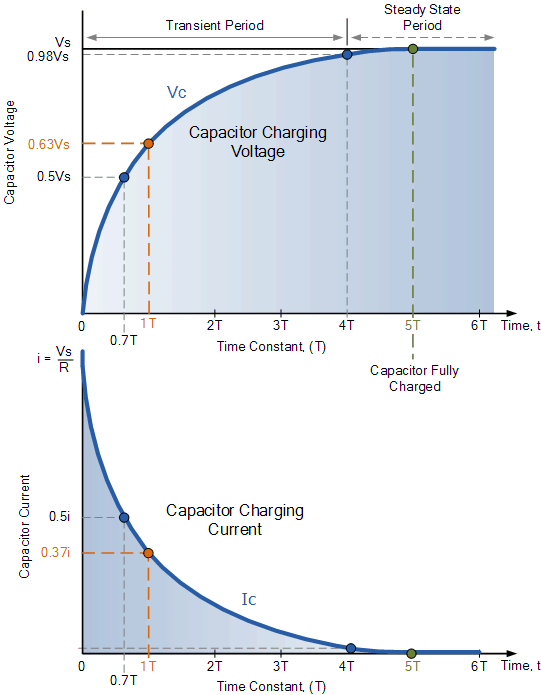
The capacitor (C) charges at the rate depicted in the graph. Because the charging rate is fastest at the start of the charge, the rise in the RC charging curve is considerably steeper at first, but it rapidly tapers off exponentially as the capacitor takes on extra charge at a slower pace.
As the capacitor charges up, the potential difference across its plates increases, with the time it takes for the charge on the capacitor to reach 63 percent of its maximum possible fully charged voltage, 0.63Vs in the curve, is known as one full Time Constant (T). 1T is the symbol for this 0.63Vs voltage point (one time constant).
As the capacitor charges up and the voltage differential between Vs and Vc decreases, the circuit current also follows this trend. The capacitor is said to be fully charged when its ultimate condition is bigger than five time constants (5T), t =∞, I = 0, q = Q = CV. When the charging current reaches zero at infinity, the capacitor behaves like an open circuit, with the supply voltage value Vc = Vs applied entirely across the capacitor.
As a result, the time necessary for a capacitor to charge up to one time constant, (1T), may be expressed mathematically as RC Time Constant, Tau:
\tau =R\times C
This RC time constant simply indicates a charge rate, with R in Ω and C in Farads.
Because the voltage V is proportional to the charge on a capacitor (Vc = Q/C), the voltage across the capacitor (Vc) at any point during the charging period is given as:
{V}_{C}={V}_{S}(1-{e}^{\frac{-t}{RC}})
Where:
Vs is the supply voltage
Vc is the voltage across the capacitor
t is the elapsed time since the application of the supply voltage
RC is the time constant of the RC charging circuit
e is an irrational number presented by Euler as: 2.7182
The capacitor in this RC charging circuit is said to be nearly fully charged after a period equivalent to four time constants (4T) because the voltage created between the capacitor’s plates has now reached 98 percent of its maximum value, 0.98Vs. The Transient Period is the amount of time it takes for the capacitor to reach this 4T point.
The capacitor is now considered to have fully charged after a duration of 5T, with the voltage across the capacitor (Vc) being about equal to the supply voltage (Vs). As a result of the capacitor being fully charged, there is no more charging current flowing in the circuit, hence IC = 0. The Steady-State Period is the time that follows the 5T period.
RC Charging Table
The percentage voltage and current values for the capacitor in an RC charging circuit for a particular time constant can therefore be shown in the table below.
| Time Constant |
RC Value |
Percentage of Maximum | |
| Voltage | Current | ||
| 0.5 time constant | 0.5T = 0.5 RC | 39.3 | 60.7 |
| 0.7 time constant | 0.7T = 0.7 RC | 50.3 | 49.7 |
| 1.0 time constant | 1.0T = 1.0 RC | 63.2 | 36.8 |
| 2.0 time constant | 2.0T = 2.0 RC | 86.5 | 13.5 |
| 3.0 time constant | 3.0T = 3.0 RC | 95.0 | 5.0 |
| 4.0 time constant | 4.0T = 4.0 RC | 98.2 | 1.8 |
| 5.0 time constant | 5.0T = 5.0 RC | 99.3 | 0.7 |
The charging curve for an RC charging circuit is exponential, not linear, as you might expect. This indicates that the capacitor will never be fully charged in reality. For all practical purposes, it reaches 99.3 percent charge after five time constants (5T), hence the capacitor is regarded as fully charged at this point.
We can compute the value of capacitor voltage, Vc, at any given point, for example, because the voltage across the capacitor Vc fluctuates with time and has a different value at each time constant up to 5T.
The Working Theory of an RC Coupled Amplifier in Electronics
Amplification is the technique of boosting a signal’s strength by raising its amplitude without changing its properties. An RC coupled amplifier is a component of a multistage amplifier that connects several stages of amplifiers using a resistor and a capacitor. One of the most fundamental circuits in electronics is the amplifier.
A transistor amplifier is a type of amplifier that is fully reliant on transistors. A current, voltage, or power signal can be used as the input signal. The signal is amplified without affecting its properties, and the output is a modified version of the original signal. Amplifiers have a wide range of applications. They’re mostly found in audio and visual instruments, as well as communications and controls.
Single Stage Common Emitter RC Circuit Amplifier
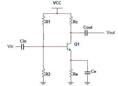
The following is a circuit diagram for a single-stage common emitter transistor amplifier:
Circuit Explanation
A simple and basic amplifier circuit is a single-stage common emitter RC coupled amplifier. The major aim of this circuit is pre-amplification, which is the process of making weak signals stronger enough to be amplified further. This RC coupled amplifier can provide good signal qualities if correctly designed.
The input capacitor (Cin) functions as a filter, blocking DC voltage and allowing only AC voltage to reach the transistor. Any external DC voltage that reaches the transistor’s base will change the biasing conditions and affect the amplifier’s performance.
The R1 and R2 resistors are employed to ensure that the bipolar transistor is properly biased. The biasing network formed by R1 and R2 provides the necessary base voltage to drive the transistor inactive region.
The active region is the area between the cut-off and saturation regions. A cut-off region is where the bipolar transistor action is totally turned off, while a saturation region is where the transistor is completely turned on.
To lower the voltage of Vcc, resistors Rc and Re are utilized. The resistor Rc is a collector resistor, while the resistor Re is an emitter resistor. Both are chosen so that in the above circuit, they should lower Vcc voltage by 50%. Negative feedback is created by the emitter capacitor Ce and emitter resistor Re, which makes the circuit more stable.
Steps To Draw a Phasor Diagram for an RC Circuit
Current I is considered as reference and voltage reduction in resistance is (VR). So, VR = IR is drawn in phase with the current I. Voltage reduction in capacitive reactance is (VC). As a result, VC = IXC (where XC is 1/2πfc) and is drawn 90 degrees behind the current (in a pure capacitive load circuit, current leads voltage by 90 degrees). The applied voltage is equal to the vector sum of the two voltage decreases (V).
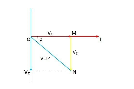
Now in the right-angle triangle OMN
V=\sqrt{{V}_{R}^{2}+{V}_{C}^{2}}=I\sqrt{{R}^{2}+{X}_{C}^{2}}
So I=V/Z Where Z= √R2 +X2C
The overall opposition presented to the flow of current in an RC series circuit is known as Z, and it is defined as the total impedance of the circuit. This is measured in ohms.
Buy Equipment or Ask for a Service
By using Linquip RFQ Service, you can expect to receive quotations from various suppliers across multiple industries and regions.
Click Here to Request a Quotation From Suppliers and Service Providers
Read More In Linquip
- Types of Electric Circuits: All Classification with Application
- What is Linear Circuit
- What is RLC Circuit
- What is Capacitive Circuit?
- Types of Resistor: Classification, Application, and Finally Clarification
- What is Parallel Circuit? Definition & Example
- What is Series Circuit? Definition & Example
- What is Closed Circuit? Definition & Example
- What is Short Circuit? A Clear Definition & Protection Guide
- Difference Between Linear and Nonlinear Circuits
- What are the Differences Between Series and Parallel Circuits?
- The 8 Best Circuit Breaker Locators
- What is LC Circuit? Formula, Equitation & Diagram
- What is Open Circuit? Diagram & Example
- What is Inductive Circuit?
- What is AC Circuit and Its Characterization?
- Circuit Breaker vs Fuse- What are the Main Differences?
- How does a Circuit Breaker Work?
- What is the Equivalent Circuit of Transformer?
- Potentiometer Connection, Working, Circuit Diagram, & Wiring Guide
- Difference Between Relay and Circuit Breaker: Everything You Need to Know
- Difference Between Isolator and Circuit Breaker: Ultimate Guide
- Piezoelectric Transducer and Its Impressive Applications in Electric Circuits
- What is Vacuum Circuit Breakers?
- Types of Circuit Breaker: A Basic Guide to Know Different Classifications



this is alot!!!!!!!!!!!!!!!!!! im gonna fail my course
Awal, We appreciate you taking the time to check out our site and share your thoughts. We look forward to your continued participation in our forums.
I appreciate your column, only that you failed to illustrate the actual calculation how the value of say 0.7RC is arrived. I need a clear process of computing the value of Vc for each time constant. Hoping you can provide my request. Thank you so much.