What exactly is the RL Circuit? An RL circuit (sometimes called an RL filter or RL network) is an electrical circuit made up of the passive circuit elements of a resistor (R) and an inductor (L) linked together and driven by a voltage or current source. An RL circuit, like an RC or RLC circuit, will consume energy due to the inclusion of a resistor in the ideal version of the circuit.
We at Linquip will do our very best to provide as many details about electrical circuits on the website as possible. For any questions regarding RL circuits and the equipment associated with them, Linquip is the best platform from which to obtain the answers. Whenever you have questions or concerns about any of these electrical devices, Linquip’s experts are ready to help. We recommend checking out Linquip’s article titled, “What Is Electrical?“. This article provides a great overview of the concept.
If you want to use the Linquip platform to its fullest potential, you first have to register as a Linquip Expert. To do so, there is a very simple process. It is possible to create an account with Linquip to display your skills related to industrial equipment in a way that is tailored to the needs of the industry. Do you want to contribute to the Linquip website as a guest poster? Your content can be directly published to Linquip’s platform using the Guest Posting option.
What is an RL Circuit?
The basic passive linear circuit parts are the resistor (R), inductor (L), and capacitor (C). These components are used to create an electrical circuit in four different methods like the RL, LC, and RLC circuits. Because of their great performance, these circuits are vital in analog electronics. In general, capacitors and inductors are preferred over other fundamental components because they are easier to manufacture.
These elements are modest in size but have high component values. Both the RL and RC circuits can be used to create a single-pole filter. When reactive elements such as a capacitor or inductor are linked in series or parallel with the load, the filter’s high-pass or low-pass characteristics are determined. The RL circuits are commonly employed in RF amplifiers and DC power supplies, where the inductor (L) generates DC bias current and prevents RF from reaching back into the power supply.
Definition of an RL Circuit
An RL circuit, also known as an RL filter, resistor–inductor circuit, or RL network, is a circuit that can be constructed using passive circuit components such as resistors and inductors and connected to a current or voltage source. This circuit will consume energy similarly to an RC/RLC circuit due to the presence of a resistor R in the ideal version of the circuit.
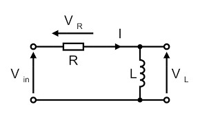
This is not the same as the ideal form of an LC circuit, which consumes no energy due to the lack of a resistor. Even though this is the circuit’s ideal form traditionally. Due to the lack of a resistor and connecting wires, even an inductor-capacitor circuit will consume some energy.
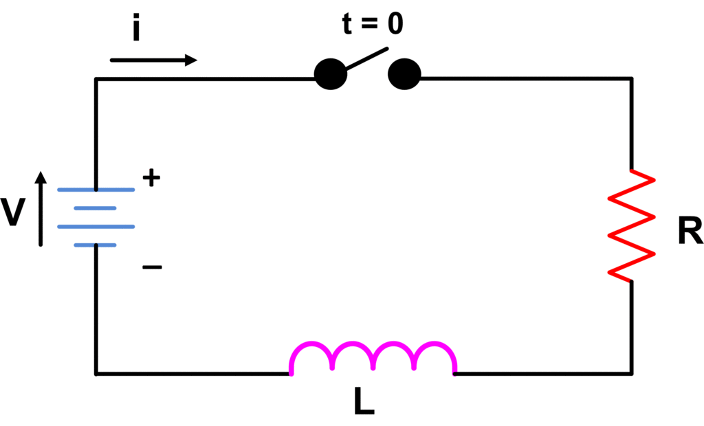
Consider the RL circuit, which uses a voltage supply to power a resistor and inductor. Assume current flow within the circuit is I (amp), current flow through the resistor is IR, and current flow through the inductor is IL.
Because both R and L are connected in series, the current flow within both components and across the circuit will be the same, as IR = IL = I. VR & VL are the voltage drops across the resistor and inductor, respectively.
When we apply the Kirchhoff voltage law to this circuit (i.e. the sum of the voltage drops must equal the applied voltage), we have V= VR + VL.
Power Factor
The RL circuit, also known as a resistor-inductor circuit, is an electric circuit made up of resistors and inductors coupled to a voltage or current source. To build an RL circuit, a first-order RL circuit consists mostly of one resistor and one inductor. Because of the inductive load, such as a 3-phase induction motor, the power factor of this circuit is low. Lamps, transformers, and welding equipment all have low trailing power factors.
Due to the inductor effect, the current flow in the RL series circuit lags behind the voltage by an angle ‘’. As a result, the power factor (PF) can be expressed as the cosine of the lagging angle. Cos ϕ = Resistance/Impedance = R/Z is the power factor.
Cos\Phi =\frac{1}{\sqrt{1+({\omega L/R})^{2}}}
In fact, when we have a small power factor like ωL>>R, the ‘1′ in the denominator becomes irrelevant. So, Cos(ϕ) = R/ω L.
Phasor Diagram of RL Circuit
The RL Series circuit’s phasor diagram is illustrated below:
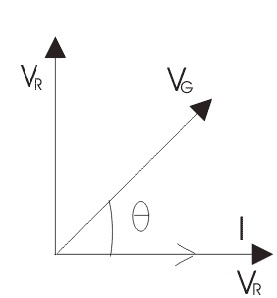
The following steps give instructions step by step to draw the phasor diagram.
Current (I) can be used as a starting point. Through the current, the VR, also known as the voltage drop across the resistance is equal to IR, can be pulled in phase. The voltage drop across the inductive reactance is VL = IXL, which can be drawn ahead of the current flow because of current lags voltage through a 90-degree angle within the inductive circuit. VR and VL are two voltage vector sum drops that are equivalent to the given voltage V.
So, in the above triangle like OAB VR = IR and VL = IXL where XL = 2πfLRL
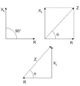
I=\frac{V}{Z} where, Z=\sqrt{{R}^{2}+{X}_{L}^{2}}
The total resistance offered to the flow of AC through an RL Series circuit is referred to as ‘Z.’ It’s called the RL circuit’s impedance, and it’s measured in ohms (Ω).
Phase Angle
The phase angle is the angle at which the current flow lags the voltage in an RL series circuit.
\phi ={tan}^{-1}\frac{{X}_{L}}{R}
The Impedance of Series RL Circuit
The impedance of the series RL circuit resists current flow, and it is nothing more than the entire circuit’s combination of resistance (R) and inductive reactance (XL) effect.
RL Parallel Circuit
The RL parallel circuit is formed when both the resistor and the inductor are joined in parallel through each other and are powered by a voltage source. Vin and Vout are the input and output voltages of the circuit. The Vin is equal to Vout once the resistor and inductor are connected in parallel. The current flow within these components, however, is not the same.
Because the input and output voltages in this circuit are equal, it cannot be utilized as a voltage filter. As a result, this circuit is not commonly utilized as an evaluator of series RL circuit. Visit here to see the main differences between series and parallel RL circuits.
Phasor Diagram
The vector (phasor) diagram can be used to show the main relationship between the voltage and currents in a parallel RL circuit. The voltage within the RL parallel circuit is represented by the reference vector ‘E’. Because the current flowing through the resistor is in phase with the voltage across it, IR appears on the voltage vector.
The ‘IL‘ lags the voltage at a 90-degree angle and can be positioned in a downward direction to lag the voltage vector at a 90-degree angle. Both vector additions, such as IR and IL, yield a value that denotes the sum (IT) otherwise line current. The phase between the provided line current and voltage is shown by the angle ‘θ’. The phasor diagram for the Parallel RL circuit is shown below.
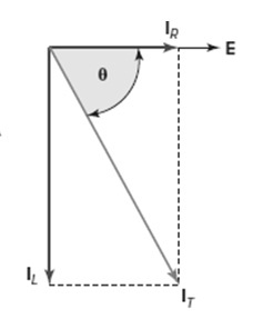
In a parallel circuit, the current flowing through each branch of the circuit operates independently of the currents flowing through the remaining branches. The voltage across the branch and the resistance to current flow in the form of either inductive reactance or resistance incorporated inside the branch can be used to determine the flow of current in each branch. The current in each branch can be calculated using Ohms law, so IR = E/R and IL = E/XL.
The current flow in a resistive branch has a phase that is identical to the provided voltage; whereas, the current in an inductive branch lags the given voltage by 90 degrees. As a result, the entire line current contains IR and IL that are 90 degrees out of phase with each other.
The legs of a right triangle are formed by the flow of current in both components, while the hypotenuse is formed by the entire current. As a result, the Pythagorean theorem is utilized to combine these currents using the following equation:
{I}_{T}=\sqrt{{I}_{R}^{2}+{I}_{L}^{2}}
The phase angle by which the entire current lags the voltage in these circuits might be anywhere between 0 and 90 degrees. As a result, whether there is an additional inductive current or a resistive current determines the angle size.
The phase angle ‘’ will be closer to 90 degrees if there is an additional inductive current. If there is an additional resistive current, it will be closer to zero degrees. As can be seen from the circuit vector diagram above, the phase angle value may be calculated using the following equation:
\Theta ={tan}^{-1}\frac{{I}_{L}}{{I}_{R}}
The impedance of an RL Parallel Circuit
A parallel RL circuit’s impedance can be defined as the total resistance to current flow. It includes both the resistance provided by the resistive ‘R’ branch and the inductive reactance ‘XL‘ provided by the inductive branch.
The impedance of a parallel RL circuit can be calculated similarly to that of a parallel resistive circuit. R and XL, on the other hand, are vector values and should be included vectorially. As a result, a parallel RL circuit’s impedance equation contains a single resistor and inductor. As a result, the parallel RL circuit’s impedance formula is
Z=\frac{R{X}_{L}}{\sqrt{{R}^{2}+{X}_{L}^{2}}}
The vector sum of the resistance and inductance resistance is in the denominator of the above equation. So, if there is more than one resistive and inductive branch, they must be equivalent for the entire resistance, or else the reactance of these parallel branches will be different.
Once the total current and applied voltage are known, impedance can be measured more easily using Ohm’s law as Z = E/IT.
When compared to the resistance or otherwise inductive reactance of any branch, the parallel RL circuit’s impedance is always low. Because of this, each branch creates a separate lane for current flow, lowering the overall circuit resistance to current flow. When the branch has the maximum current, it has the greatest impact on the phase angle. As a result, this is a series RL circuit in reverse.
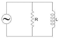
When inductance exceeds resistance in a parallel RL circuit, the resistive branch current outperforms the inductive branch current. As a result, because it is more responsive in nature, the phase angle between the provided voltage and the total current can be closer to 0 degrees.
RL Circuit Uses
Different circuits, such as RC, RL, and RLC circuits, are formed by combining fundamental components such as resistors, capacitors, and inductors. The following are examples of RL circuit applications.
- Filtering Circuits
- RF Amplifiers
- Processing of Signal
- Communication Systems
- Magnification of Current or Voltage
- Oscillator Circuits
- Radio Wave Transmitters
- Variable Tunes Circuits
- Resonant RL Circuit
Because the inductor (L) is utilized to supply DC bias current and restrict the RF from reaching the power source, these circuits are employed as DC power supplies within RF amplifiers.
What Is the Difference between RL and RC Circuits?
The RC circuit stores energy as an electric field when resistance and capacitance are connected in series. On the other hand, an RL circuit stores energy in the form of magnetic energy as a combination of resistance and inductance.
Download RL Circuit PDF
By clicking on the following link, you will be able to download a PDF file that contains all the content of this article.
Thus, an overview of the RL Circuit, RL series circuit, RL parallel circuit, phasor diagram, and its applications are presented. Let us ask you a question: what are the benefits of RL circuits? Share your comment below.
Buy Equipment or Ask for a Service
By using Linquip RFQ Service, you can expect to receive quotations from various suppliers across multiple industries and regions.
Click Here to Request a Quotation From Suppliers and Service Providers
Read More In Linquip
- Types of Electric Circuits: All Classification with Application
- How does a Circuit Breaker Work?
- What is Linear Circuit
- What is RC Circuit?
- What is RLC Circuit
- What is Capacitive Circuit?
- Types of Resistor: Classification, Application, and Finally Clarification
- What is Parallel Circuit? Definition & Example
- What is Series Circuit? Definition & Example
- What is Closed Circuit? Definition & Example
- What is Short Circuit? A Clear Definition & Protection Guide
- Difference Between Linear and Nonlinear Circuits
- What are the Differences Between Series and Parallel Circuits?
- The 8 Best Circuit Breaker Locators in 2022
- What is LC Circuit? Formula, Equitation & Diagram
- What is Open Circuit? Diagram & Example
- What is Inductive Circuit?
- What is AC Circuit and Its Characterization?
- Circuit Breaker vs Fuse- What are the Main Differences?
- How does a Circuit Breaker Work?
- What is the Equivalent Circuit of Transformer?
- Potentiometer Connection, Working, Circuit Diagram, & Wiring Guide
- Difference Between Relay and Circuit Breaker: Everything You Need to Know
- Difference Between Isolator and Circuit Breaker: Ultimate Guide
- Piezoelectric Transducer and Its Impressive Applications in Electric Circuits
- What is Vacuum Circuit Breakers?
- Types of Circuit Breaker: A Basic Guide to Know Different Classifications



Very helpful, thank you.
Thanks for sharing your experience with us, Lawrence! You can also visit our industrial directories, where you can find thousands of various industrial equipment based on your application and demand.