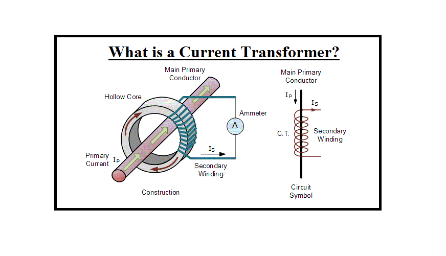
A current transformer is an instrument that is used for the transformation of current from a greater value into a proportionate output to a lower amount. It transforms the large-voltage current into the low-voltage current, due to which the heavy current moving across the transmission lines are safely controlled by the ammeter.
What is the Current Transformer?
The Current Transformer (C.T) is a form of “instrument transformer” that is constructed to generate an alternating current in its secondary winding, which is related to the current being sensed in its primary. Current transformers decrease the high-voltage values to a much lower current and supply a convenient method of safely measuring the actual electrical current moving in an AC transmission line applying a standard ammeter. The working principle of a standard current transformer is moderately different from that of an ordinary voltage transformer.
The current transformer is used in the AC device, meters, or monitoring apparatus where the current to be sensed is of such magnitude that the instrument coil or meter cannot conveniently be created from adequate current carrying capacity.
Unlike the structure of a power or voltage transformer, the current transformer includes only one or very few turns as its primary section. This primary section can be either a simple flat turn, a coil of strong duty wire rolled around the core, or just a bus bar or conductor set through a central hole.
Based on this form of configuration, the current transformer is always introduced as a “series transformer” as the primary section, which never has more than a very few turns, is in series form with the current-carrying conductor providing a load.
The primary current and secondary output of the current transformers are related to each other. The current transformer is employed for sensing the high-voltage current due to the difficulty of insufficient insulation in the meter itself. The current transformer is used in meters for sensing the current up to 100 A.
The secondary part, however, may have a great number of coil rolls wound on a laminated component of low-loss magnetic material. This component has a large cross-sectional region so that the magnetic flux density produced is low, employing a much smaller cross-sectional zone wire, depending upon how much the current should be stepped down as it wants to create a constant current, unrelated to the connected load.
The secondary section will provide a current into a resistive load or into either a short circuit, in the form of an ammeter until the voltage generated in the secondary is heavy enough to saturate the core or result in a failure from additional voltage breakdown.
Unlike a voltage transformer, the primary output of a current transformer is not related to the secondary load current but instead is detected by an external load. The secondary output is commonly rated at a standard 1 A or 5 A for greater primary current ratings.
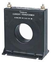
There are three main kinds of current transformers: toroidal, wound, and bar.
Toroidal Current Transformers: These do not include a primary winding. Instead, the line that runs the current flowing in the system is threaded across a hole or window in the toroidal transformer. Some current transformers contain a “split core” which permits them to be opened, installed, and closed without disconnecting the system to which they are joined.
Wound Current Transformers: The transformer’s primary section is physically configured in series form with the conductor that carries the detected current flowing in the system. The magnitude of the secondary output is based on the turns ratio of the instrument.
Bar-type Current Transformers: This form of current transformers employs the actual wire or bus-bar of the main circuit as the primary section, which is identical to a single turn. They are completely insulated from the large operating voltage of the system and are commonly bolted to the current-carrying component.
Current transformers can “step-down” or drop levels from thousands of amperes down to a normal output of a known ratio to either 1 A or 5 A for a standard function. Thus, accurate and small instruments and monitoring devices can be applied with CTs since they are insulated away from any high-voltage energy lines. There are several metering cases and usages for current transformers, such as with power factor meters, Wattmeter’s, protective relays, watt-hour meters, or as trip coils in MCBs or magnetic circuit breakers.
Construction of a Current Transformer
The center of the current transformer is accumulated with lamination of silicon steel. The Mumetal or Permalloy is used for making cores to obtain a high degree of accuracy. The primary section of the current transformers carries the current which should be measured, and it is attached to the main circuit. The secondary windings of the transformer carry the current proportional to the current to be measured, and it is connected to the current windings of the meters or the instruments. Visit here to explore more about the construction of a current transformer.
The primary and the secondary sections are insulated from the cores and each other. The primary section is a simple turn winding (also introduced as a bar primary) and carries the full-load current, while the secondary part of the transformers has several turns.
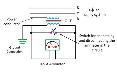
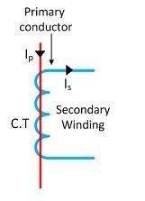
The level of the primary and the secondary output is introduced as a current transformer rate of the system. The current rate of the transformer is normally high. The secondary current rates are of the order of 0.1 A, 1 A, and 5 A. Uncommon current primary rates differ from 10 A to 3000 A or more. The symbolic symbol of the current transformer is presented in the figure below.
Working Principle of a Current Transformer
The working principle of a current transformer is especially different from the power transformer. The load’s impedance or burden on the secondary component has moderately differed from the power types in a current transformer. Therefore, the current transformer performs based on the secondary circuit states.
The burden on a Load
The burden of a current transformer is the amount of the load generated within the secondary winding. It is presented as the output in V.A (volt-amperes). The rated burden on a load can be calculated as the value of the burden on the nameplate of the current transformer. The rated burden of the system is of the voltage and current on the secondary winding when the CT supports the relay or instrument with its maximum rated amount of the current.
Current Transformer Equation
In general, current transformers and ammeters are employed together as a particular pair in which the model of the instrument is such as to supply a maximum secondary current controlled by a full-scale deflection on the ammeter. An approximate inverse turns level exists between the two currents in most current transformers in the secondary and primary windings. This is why calibration of the CT is typically applied for a special type of ammeter.
Most current transformers have the normal secondary rating of 5 A, with the secondary and primary currents being presented as a ratio such as 5/100. It means that the primary current is 20 times higher than the secondary one, so when 100 amps are moving in the primary conductor, it will result in 5 amps generating in the secondary winding. A current transformer of say 5/500 will create 5 amps in the secondary winding for 500 amps in the primary part, 100 times higher.
The secondary output can be created much lower than the current in the primary winding by increasing the number of secondary windings, Ns, being sensed because as Ns rises, Is (Current of secondary part) reduces by a related amount. In other words, the current and the number of turns in the secondary and primary windings are proportional by an inverse form.
A current transformer, like any other type of transformer, should satisfy the amp-turn formula. This turns ratio is equal to:
T.R=n=\frac{{N}_{P}}{{N}_{S}}=\frac{{I}_{S}}{{I}_{P}}
from which we obtain:
Secondary Current, {I}_{S}={I}_{P}(\frac{{N}_{P}}{{N}_{S}})
The current rate will determine the turn ratio, and as the primary winding commonly includes one or two turns, whereas the secondary winding can include several hundred turns, the rate between the primary and secondary can be relatively large. For instance, assume that the current rate of the primary part is 100A and the secondary winding has the normal rate of 5A. The 100 to 5 and 20 to 1 types are the most common forms of current transform existence in the market.
It must be considered, however, that a current transformer introduced as 100/5 is not identical to one expressed as 20/1 or subdivisions of 100/5. This is due to the fact the ratio of 100/5 presents the “input/output current rating” and not the practical ratio of the primary to the secondary outputs. Also, consider that the number of rolls and the current in the secondary and primary windings are related by an inverse ratio.
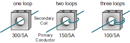
But relatively great variations in a current transformer turns ratio can be obtained by varying the primary rolls within the CT’s window where one primary turn is identical to one pass and more than one pass across the window causes the electrical ratio to be modified.
So, for instance, a current transformer with a ratio of, say, 300/5 can be modified to another of 150/5 or even 100/5 by passing the basic primary conductor within its interior window two or three times. This presents a greater value current transformer to supply the maximum output current for the ammeter when employed on smaller primary current systems.
Read More on Linquip
- Current Transformer Types and Applications
- Types of Transformer: An Article About How Transformers Differ in Construction and Design
- What is Potential Transformer?
- What is Power Transformer?
- working principle of transformer: discover the mechanism involved in the operation
Effect of Open Secondary Windings of a Current Transformer
Under normal performance states, the secondary winding of a current transformer is attached to its burden, and it is normally closed. When the current moves across the primary part, it often flows within secondary windings, and amperes turns of each section are subsequently identical and opposite.
The secondary rolls will be 1% and 2% less than the primary ones, and the difference being employed in the magnetizing core. As a result, if the secondary component is opened and the current moves across the primary windings, then there will be no demagnetizing environment because of the secondary current.
Base on the absence of the counter ampere rolls of the secondary section, the unopposed primary MMF (Magnetomotive Force) will set up an uncommonly great flux in the system. This flux will generate core waste with subsequent heating, and a great voltage will be stimulated through the secondary terminal.
This voltage resulted in the breakdown of the insulation, and also the waste of accuracy in the future can occur since the additional MMF leaves the residual magnetism in the system. Therefore, the secondary of the current transformer may never be open when the primary part is carrying the current.
Phasor Diagram of Current Transformer
The phasor diagram of the current transformer is illustrated in the figure below. The basic flux is taken as a reference. The secondary and primary produced voltages are lagging behind the basic flux by 90º. The magnitude of the primary and secondary voltages depends on the number of rolls on the windings. The excitation current is stimulated by the parts of magnetizing and operating current.
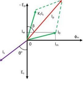
Where Is is the secondary current, Es is the secondary induced voltage, Ip is the primary current, Ep is the primary induced voltage, Kt is turn ratio, or the number of secondary turn/number of primary turn, I0 is the excitation current, Im is the magnetizing current, Iw is the working component, and Φs is main flux.
The secondary output lags behinds the secondary stimulated voltage by a particular angle (θº). The secondary current replaces the primary side by reversing the secondary output and multiply by the turn rate. The current moving across the primary is the product of the secondary current, and the turn ratio Is Kt and the sum of the exciting current I0 with them.
Ratio and Phase Angle Errors of CT
The current transformer includes two problematic errors that are ratio error and a phase angle error.
Current Ratio Errors
The current transformer is mostly based on the energy component of excitation output and is obtained as
Ratio_{Error}= \frac{{K}_{t}{I}_{s}-{I}_{P}}{{I}_{P}}
Where Kt is the turn ratio, Ip is the primary current, and Is is the secondary current.
Phase Angle Error
In a perfect current transformer, the vector angle between the reversed secondary and primary current is zero. But in a practical current transformer, there is a phase difference between the secondary and the primary current since the primary output has also supplied the portion of the exciting current. Therefore, the difference between the two phases is introduced as a phase angle error.
Current Transformer Primary Turns Ratio
A current transformer should never be left in open-circuited condition or performed with no-load connected when the basic primary current is moving across it, just as a voltage transformer type should never perform on a short-circuit condition. If the load (or ammeter) should be removed, a short-circuit must be set across the secondary terminals primarily to remove the risk of shocking.
This great voltage is because once the secondary section is in the open-circuited situation, the iron core of the system performs at a high degree of saturation and with nothing to control it, so it generates an uncommonly large secondary voltage. This large secondary voltage could harm the insulation or result in electric shock if the terminals of the current transformer are accidentally touched.
Handheld Current Transformers
There are several specialized forms of current transformers now available in the market. A common and portable kind that can be employed to detect the circuit loading is introduced as “clamp meters” or “Handheld type,” as shown.

Clamp meters close and open around a current transporting conductor and control its current by identifying the magnetic field around it, supplying a quick measurement reading commonly on a digital display without opening or disconnecting the circuit.
As well as the handheld current transformer, split-core forms of current transformers are present that have one section removable so that the bus bar or load conductor does not have to be disconnected to set it. These are present for sensing currents from 100 A up to 5000 A, with square window forms from 25 mm to 300mm. (1″ to over 12″).
Summary
To summarize, the Current Transformer (CT) is a form of transformers employed to transform a primary current into a secondary output across a magnetic medium. Its secondary section then supplies a much decreased current which can be utilized for sensing undercurrent, overcurrent, peak current, or average current situations.
A current transformer’s primary winding is often configured in series form with the main conductor. It is also being introduced as the “series transformer”. The standard secondary current is usually rated at 5A or 1A for ease of sensing. Their structure can be one single primary turn as in Doughnut, Toroidal, or Bar forms, or a few wound primary turns, commonly for low current applications.
Current transformers are considered to be applied as proportional current instruments. Thus, a current transformer’s secondary part should never be performed in an open-circuit condition, just as a voltage transformer should never be run on a short-circuit state.
Buy Equipment or Ask for a Service
By using Linquip RFQ Service, you can expect to receive quotations from various suppliers across multiple industries and regions.
Click Here to Request a Quotation From Suppliers and Service Providers

